Golf Tee and Adapter

a technology for adapters and golf balls, applied in golf, golf accessories, golf tees, etc., can solve problems such as potential hazards, imminent dangers, and golfers being hit by other golfers' golf balls, and achieve the effect of low cos

Inactive Publication Date: 2008-06-19
DANDELIUS MORGAN
View PDF18 Cites 18 Cited by
  • Summary
  • Abstract
  • Description
  • Claims
  • Application Information

AI Technical Summary

Benefits of technology

[0010]The present invention provides a golf tee that is securely mounted on a mat, which behaves as a normal tee, which will last for long before breaking, being of low cost type, and still be mounted on any suitable position on a mat according to the need and desires of the golfer.

Problems solved by technology

Especially at the driving range, one problem with conventional tees is that they tend to be catapulted out onto the driving range, and there is a potential hazard when the golfer goes out onto the driving range to fetch the tees.
There is an imminent danger that the golfer is hit by other golfer's golf balls.
During practice, the problem with the tee being catapulted away from the striking position, may be troublesome since the golfer is then forced to change the stance when fetching the lost tee or fetching a new tee; the important repetition moment may thus disturbed.
When the tee is catapulted away from the driving area, the tee is often lost or it may be time consuming to find the tee again.
This limits the applicability since the golfer is then restricted to stand at the location of these pre mounted tee accepting devices.
These pre mounted bases are difficult to mount since it involves lifting of the mat in order to mount the bases from the underside of the mat.
Also these pre mounted structures has a tendency to break or wear during usage and therefore need to be replaced, with considerable effort and cost for the golf club.
Also many of these solutions known previously do not behave as normal golf tees and may in fact provide the practicing golfer with a faulty impression or training situation and thus actually reduce the skill of the golfer.

Method used


Image

  • Golf Tee and Adapter
  • Golf Tee and Adapter
  • Golf Tee and Adapter

Examples


Embodiment Construction

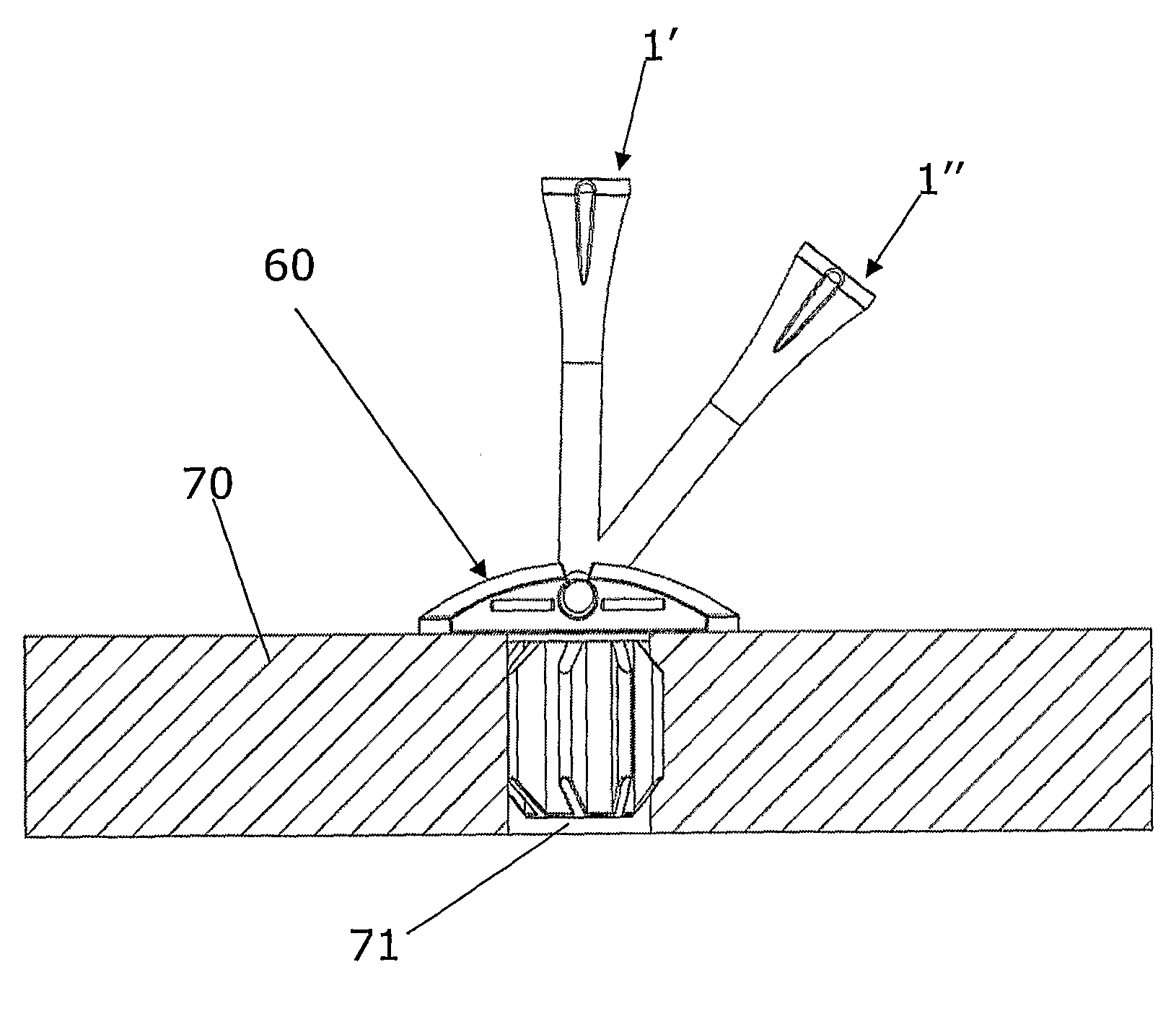
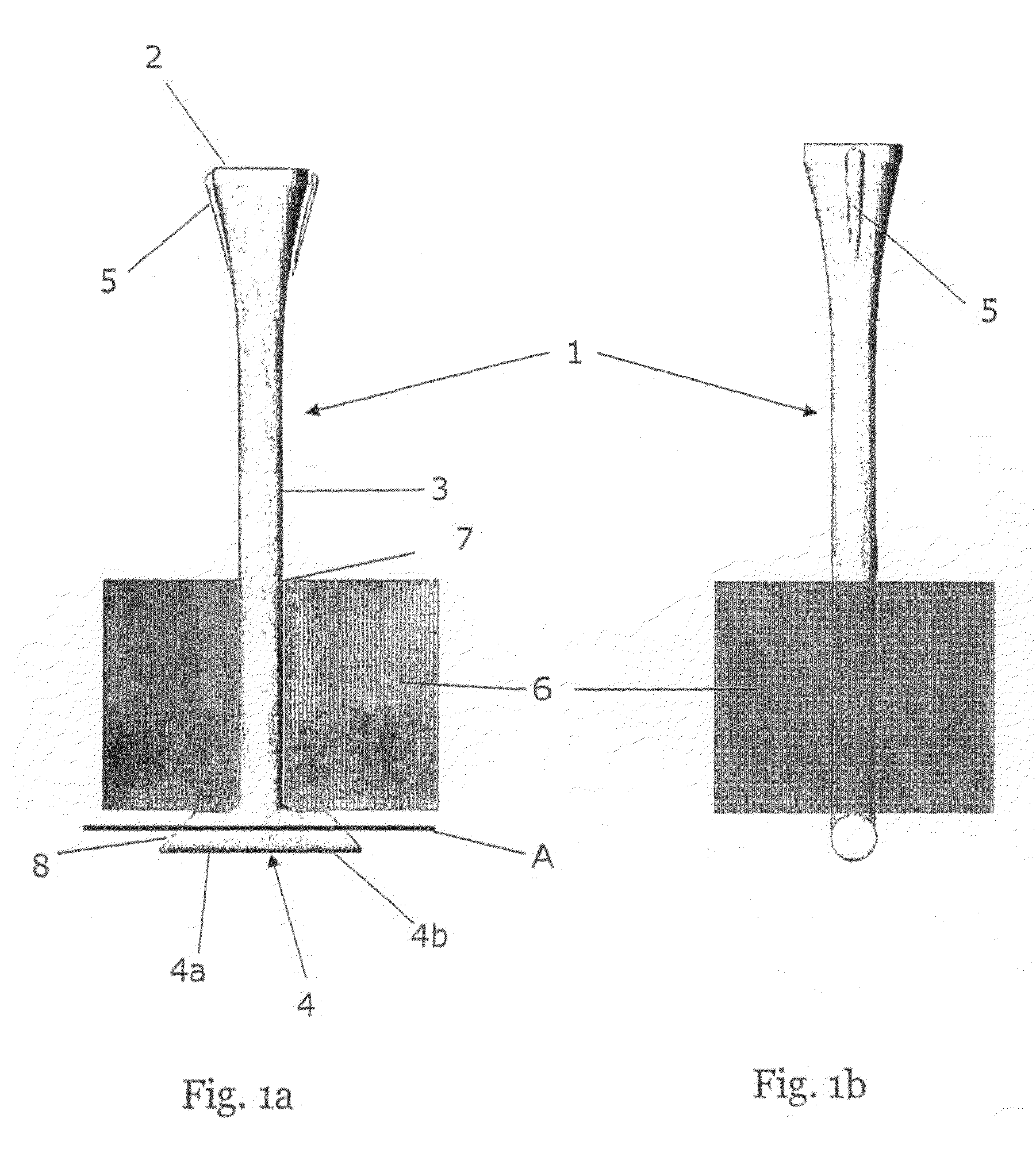
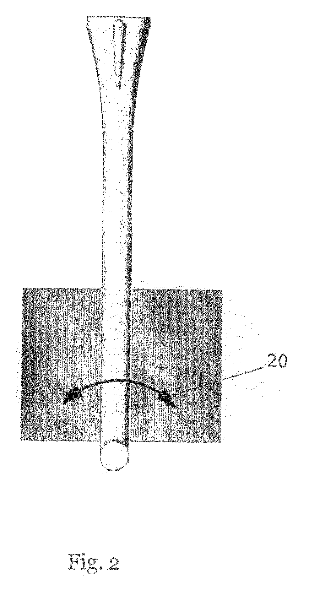
[0046]A golf tee 1 according to the present invention is shown in FIG. 1 and comprises a integrally formed unit 1 including a ball positioning platform 2, a stem 3, and a base 4 formed to lock in a structure and provide pivotal movement. The tee may further comprise at least one guiding structure 5 formed on either the platform 2 or on the stem 3 used for confirming the position of the base 4 with respect to a golf mat 6.

[0047]The base may comprise different solutions providing locking and pivotal means, such as an inverted T-shaped base (hereinafter the T-shaped base), an L-shaped base, or several elements protruding perpendicularly away from the stem 3. Below a description of a variant with a T-shaped base 4 will be given.

[0048]The T-shaped base 4 comprises two opposing protruding elements 4a, 4b mounted on the lower end of the stem 3. The ends 8 of the protruding elements 4a, 4b may or may not be inclined as will be described later. The protruding elements 4a, 4b may comprise a c...


PUM


Abstract

A golf tee (1) for use preferably on a mat comprise a base (4) providing locking (4a, 4b) and pivotal elements in the mat. The locking and pivotal elements may be provided by an inverted T-shaped base (4) that easily may be inserted into a slit (57) in the mat and there after the tee may be turned so as to slide the protruding legs (4a, 4b) of the inverted T-shaped base (4) in under the mat structure and thus locking and pivotal elements are provided. An adapter (60, 80) for mounting of the golf tee in mats with a hole instead of a slit is provided and an adapter for mounting in grass is also provided wherein the adapter is arranged to be pressed into place from above.

Description

FIELD OF THE INVENTION[0001]The present invention relates to a golf tee and in particular to a golf tee positioned on a mat or tee box and an adapter for receiving the golf tee.BACKGROUND OF THE INVENTION[0002]A golf tee is used for raising the golf ball above the ground or mat in order to get a cleaner hit and thus more powerful stroke, reaching a longer distance. The tee is mainly used for the so called “wood” clubs or drivers but may be used also for the so called “iron” clubs. The tee is only allowed during the initial drive at each hole, but is also used during practice at the driving range. A conventional tee is made as a pointy stick with a small platform at the top whereto the golf ball may be located and securely put onto. The pointy end is forced into the ground prior to striking the ball or the tee is mounted in a suitable hole or slit in a mat.[0003]Especially at the driving range, one problem with conventional tees is that they tend to be catapulted out onto the driving...

Claims


Application Information

Patent Timeline
Patent Type & Authority Applications(United States)
IPC IPC(8): A63B57/00A63B
CPCA63B57/0018A63B57/10A63B57/19A63B57/13
Inventor DANDELIUS, MORGAN
Owner DANDELIUS MORGAN
Why Eureka
Try Eureka