Evacuation system

a technology of evacuation system and dispenser, which is applied in the direction of liquid handling, instruments, pliable tubular containers, etc., can solve the problems of unsanitary conditions, prohibitive cost of dispenser and operating cost of such dispensers suitable for dispense of viscous products, and problems such as the inability to meet the needs of use and maintenance,

Inactive Publication Date: 2008-06-26
LANCER PARTNERSHIP
View PDF13 Cites 7 Cited by
  • Summary
  • Abstract
  • Description
  • Claims
  • Application Information

AI Technical Summary

Benefits of technology

[0011]In accordance with the present invention, an evacuation system including an evacuation member engages a product package and applies pressure thereto, such that a product in the product package moves toward an outlet in the product package for dispensing. The evacuation member is driven by a motor. A controller monitors the force applied to the product package to maintain the pressure below a particular threshold, thereby ensuring that the product package is not ruptured. The controller further monitors the evacuation member location, thereby enabling the controller to recognize when the product package is empty.
[0012]The evacuation system further includes a package carrier for product package loading ease. The package carrier further includes a pinch-off area that moves product out of an unrecoverable portion of the product package. The evacuation system may still further include a pump connectable to the product package and a driver that actuates the pump to evacuate product from the product package.
[0015]It is a further object of the present invention to provide a package carrier capable of aiding in the evacuation process.
[0017]It is still yet further an object of the present invention to increase the evacuation efficiency of product packages.

Problems solved by technology

Problems associated with viscous products or soups that contain solids arise because an employee or a customer typically manually dispenses such products.
These problems relate to product remnant, consistency, quality, cost, cleanliness, and the like.
This results in direct employee contact with both the dispensers and the food products.
If the dispensers are not routinely cleaned or are cleaned improperly, an unsanitary condition situation arises.
However, viscous products present other problems because the product is not conducive to being evacuated with a pump.
Thus, the final product can remain uncovered for long periods and employees or customers often contact the final product, both of which are unsanitary.
Manual dispensing of food products occurs because heretofore the cost for dispensers and operational costs of such dispensers suitable to dispense viscous products has been prohibitive.

Method used


Image

  • Evacuation system
  • Evacuation system
  • Evacuation system

Examples


second embodiment

[0110]In a second embodiment for determining the required position of the evacuation member 133, a package motor assembly 510 is used to ascertain when the evacuation member 133 has applied sufficient pressure to the package 210. The package motor assembly 510, as shown in FIGS. 11a-11b, includes an enclosure 500, a driver 185 and a microswitch 505. The enclosure 500 includes a top cover 501, a bottom cover 502 and a plurality of shoulder bolts 507. In this embodiment, the driver 185 is housed in the enclosure 500 restrained by a plurality of shoulder bolts 507. The enclosure 500 mounts onto the mid plate 105 in the area where the driver 185 currently is mounted. The driver 185 resides inside of the enclosure 500 and is mounted on shoulder bolts 507, wherein the driver 185 is able to slide vertically against a plurality of springs 506. The package motor 185 is connectable to the threaded shaft 139 as in the preferred embodiment. This embodiment further includes a microswitch 505 att...

third embodiment

[0112]In a third embodiment for determining the required position of the evacuation member 133, a package motor assembly 410 is used to ascertain when the evacuation member 133 has applied sufficient pressure to the package 210. In this embodiment, as shown in FIGS. 12a-12b, the package motor assembly 410 includes a driver 185, an enclosure 400 and a hall-effect sensor 403. The enclosure 400 includes a top cover 401, a bottom cover 402, a plurality of shoulder bolts 407 and a plurality of springs 406. The shoulder bolts 407 restrain the top cover 401 and the bottom cover 402. The enclosure 400 mounts onto the mid plate 105 in the area where the driver 185 currently is mounted. The driver 185 resides inside of the enclosure 400 and is mounted on the shoulder bolts 407, wherein the package motor 185 is able to slide vertically. The driver 185 is connectable to the threaded shaft 139 as in the preferred embodiment. This embodiment further includes a magnet 405 attached to the driver 18...

fourth embodiment

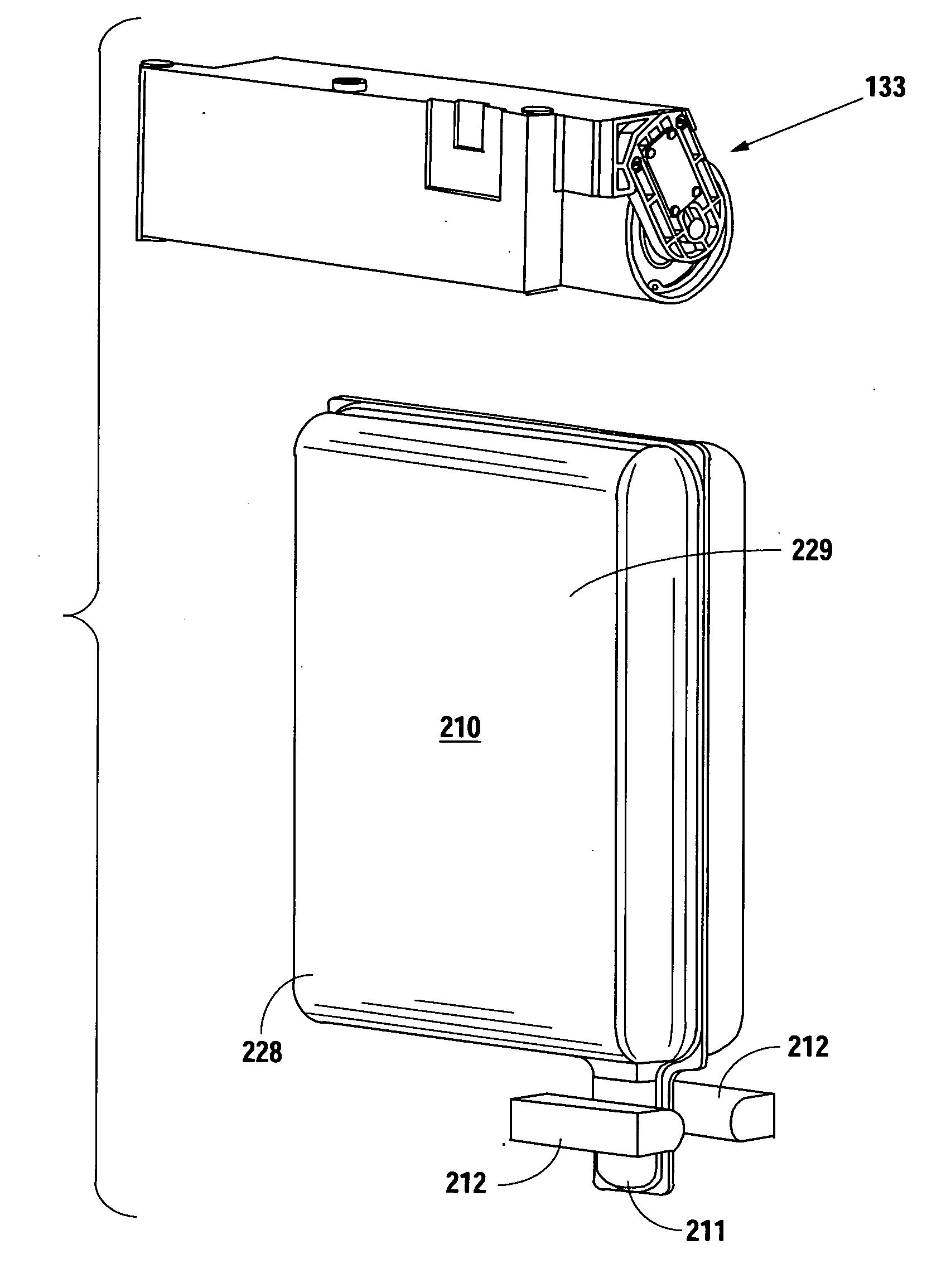
[0122]In a fourth embodiment, the backing plate assembly 130 may be replaced with a double roller evacuation unit 700 as shown in FIGS. 15a-15c. The double roller evacuation unit 700 includes a first roller 705, a second roller 710 and a carrier frame 715. The rollers are suitably mounted on the carrier frame 715 to allow a product package 210 to pass between the two rollers. As a first end 712 of the product package 210 passes between the two rollers, product is forced into a portion of the product package 210 that has not passed between the rollers. Since the product is now in a smaller volume, the product package 210 becomes pressurized. The first and second rollers 705 and 710 may have provisions to allow for fluctuations in product particle sizes, such as slight travel away from each other or spring loaded rollers. The roller frame 715 includes a frame track 725 used to restrict the roller bracket 720 to vertical motion. As the product package 210 is pressurized when the roller...


PUM


Abstract

An evacuation system including an evacuation member engages a product package and applies pressure thereto, such that a product in the product package moves toward an outlet in the product package for dispensing. A controller monitors the force applied by a driver to the product package, thereby ensuring that the pressure remains below a particular threshold to protect the integrity of the product package. The controller further monitors the evacuation member location, thereby enabling the controller to recognize when the product package is empty. The evacuation system further includes a package carrier including a pinch-off area that moves product out of an unrecoverable portion of the product package. The evacuation member may be utilized as a stand-alone device or with a primary device, wherein the primary device provides signals to the evacuation system and the evacuation system provides product to the primary device.

Description

RELATED APPLICATION[0001]The present application is a continuation application of co-pending patent application Ser. No. 11 / 418,426 filed on May 4, 2006, which is a divisional application of U.S. Pat. No. 7,086,428, issued Aug. 8, 2006.[0002]The present application claims all available benefit, under 35 U.S.C. 119(e), of U.S. provisional patent application Ser. No. 60 / 519,878, filed Nov. 13, 2003, and U.S. provisional patent application Ser. No. 60 / 467,042, filed May 1, 2003. By this reference, the full disclosures of U.S. provisional patent application Ser. No. 60 / 519,878 and U.S. patent application Ser. No. 60 / 467,043 are incorporated herein as though now set forth in its entirety.BACKGROUND OF THE INVENTION[0003]1. Field of the Invention[0004]The present invention relates to a method and apparatus for dispensing and, more particularly, but not by way of limitation, to a method and apparatus for dispensing food products and food product concentrates, such as pizza sauce, soft ice ...

Claims


Application Information

Patent Timeline
Patent Type & Authority Applications(United States)
IPC IPC(8): G01F11/00B65D35/28B67D7/08
CPCB67D1/0001B67D1/0048B67D2001/0827B67D1/0081B67D7/0255B67D1/005B67D7/0216
Inventor SCHROEDER, ALFRED A.ROMANYSZYN, MICHAEL T.GOOD, MERRILL R.SANTY, JOHN D.HERNANDEZ, GEORGE E.HOCH, RONALD RAY
Owner LANCER PARTNERSHIP
Why Eureka
Try Eureka