Packet-switched network synchronization system and method

a packet switched network and packet synchronization technology, applied in digital transmission, time-division multiplex, electrical equipment, etc., can solve the problems of complex interpretation of received packets with respect to internal timing reference systems of receiving end, inability to meet other users, and inability to achieve clock and symbol synchronization, etc., to achieve the effect of robustness, accuracy and complexity

Active Publication Date: 2008-06-26
EDGEWATER COMP SYST
View PDF2 Cites 13 Cited by
  • Summary
  • Abstract
  • Description
  • Claims
  • Application Information

AI Technical Summary

Benefits of technology

[0012]Embodiments of the system and method according to invention present advantages in terms of complexity, robustness and accuracy compared to prior-art methods.

Problems solved by technology

Even if no actual communication is taking place over a dedicated circuit, that circuitry still remains unavailable to other users.
Specifically, interpretation of a received packet with respect to an internal timing reference system of the receiving end is currently a complex aspect to tackle.
Therefore, clock and symbol synchronization for packet switched networks are generally more complex and / or less accurate than in the circuit switched networks.
Multiple access systems such as Time Division Multiple Access (TDMA) where the network is generally shared and there is typically an unknown time delay between terminals, or wireless networks with channel fading conditions or communications over power line channels where a light has been switched on, present especially difficult challenges in achieving synchronization.
This approach presents several drawbacks: firstly, preamble detection and alignment of sync symbols with an internal clock involves complex computations, therefore requiring such computations for every incoming packet results in more complex hardware requirements.
Secondly, the sync symbols detection and the decoding of the data part are carried within a single frame, for each frame, which can lead to either accuracy issues for frames with a preamble of a shorter duration, or to timing and bandwidth constraints when a longer duration preamble is used.

Method used


Image

  • Packet-switched network synchronization system and method
  • Packet-switched network synchronization system and method
  • Packet-switched network synchronization system and method

Examples


Embodiment Construction

[0022]In the following detailed description, numerous specific details are set forth in order to provide a thorough understanding of the invention. However, it will be understood by those skilled in the art that the present invention may be practiced without these specific details. In other instances, well-known methods, procedures, components and circuits have not been described in detail so as not to obscure the present invention.

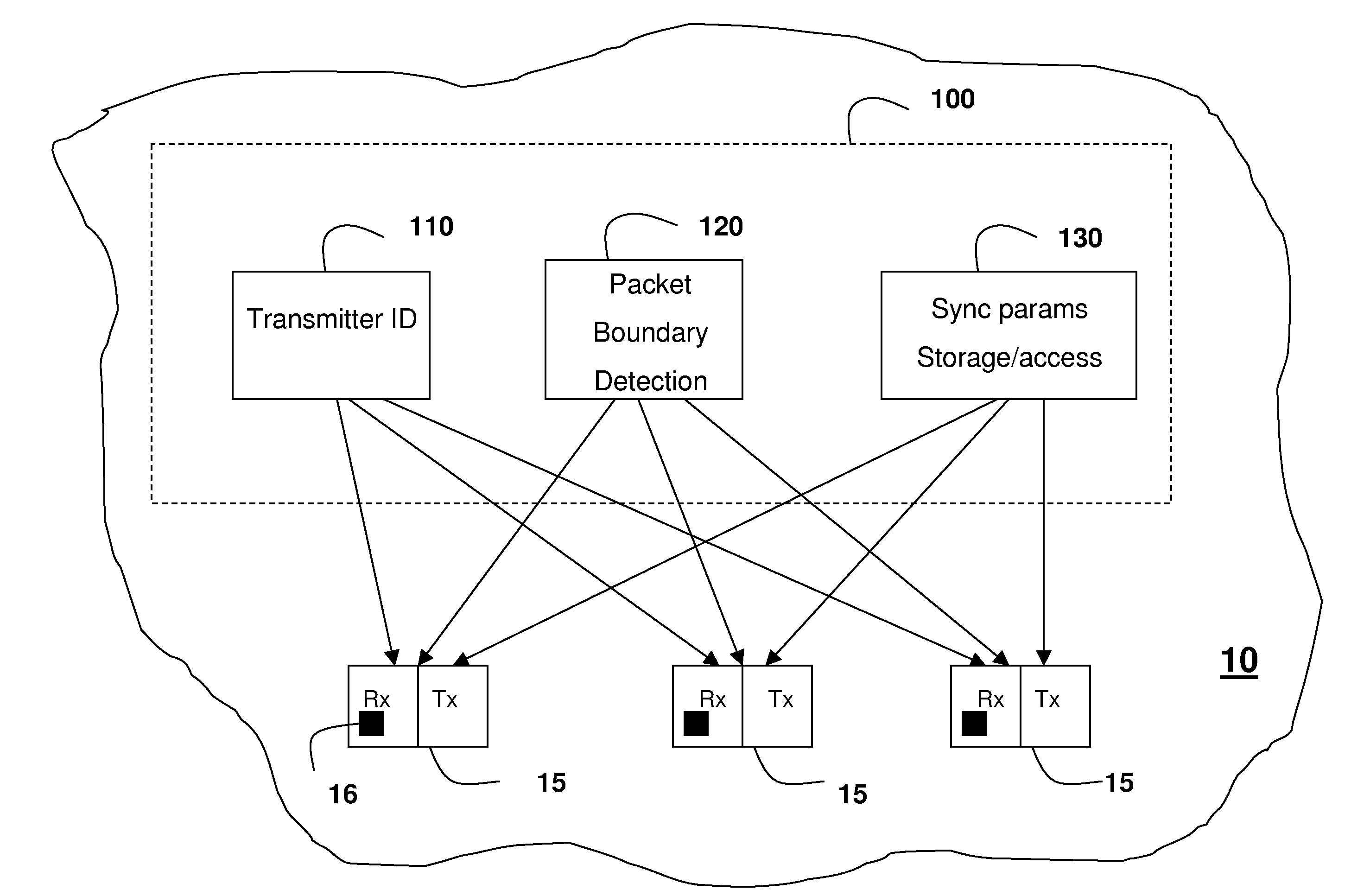
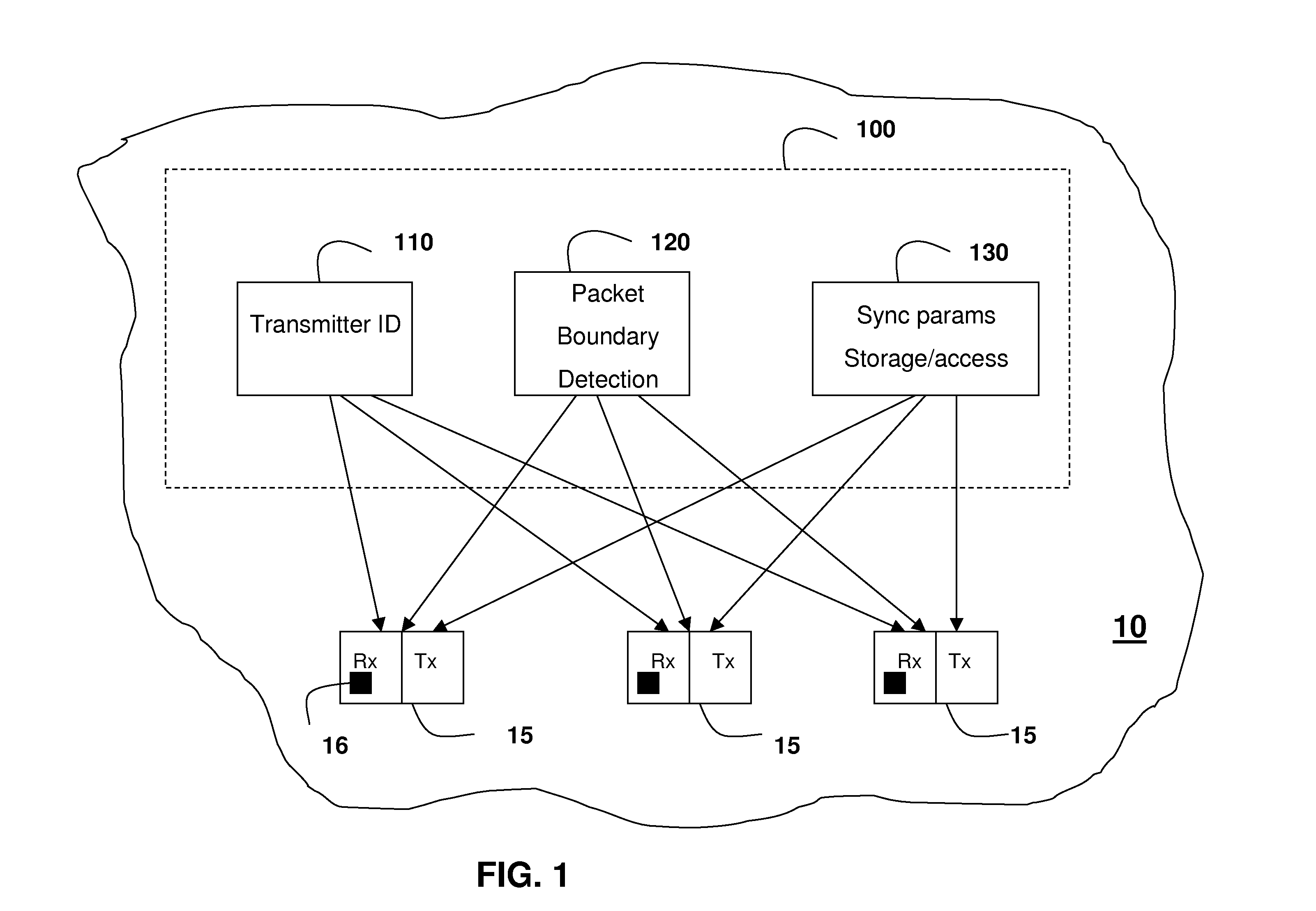
[0023]FIG. 1 illustrates a packet switched network 10 comprising a synchronization system 100 according to an embodiment of the invention. The network 10 can be any packet switched networks known in the art. Advantageously, synchronization system 100 would be used within a packet switched network 10 where the topology does not change significantly, from a signal timing point of view, over a relatively long period of time, substantially greater than the duration of a typical transmitted waveform. Most packet-based networks over fixed length connections, ei...


PUM


Abstract

A synchronization system and method for use in a packet switched communication network are provided. The synchronization system comprises a transmitter-identification system, a packet-boundary detection system and a storage-access system. The transmitter-identification system enables each receiving terminal within the network to know the identity of the originating transmitter terminal for a given packet of information, prior to the reception of this packet of information. The packet-boundary detection system enables detection of packet synchronization parameters for all transmitter-receiver pairs of terminals within the network. The storage-access system stores the detected packet synchronization parameters and allows the receiver to access the packet synchronization parameters. According to one embodiment of the invention, the synchronization method comprises the step of detecting synchronization parameters and, for a given receiver terminal, establishing the identity of the originating transmitter for an incoming packet of information, accessing synchronization parameters corresponding to the identified transmitter, adjusting receiver based on accessed synchronization parameters and decoding the incoming packet of information.

Description

BACKGROUND OF THE INVENTION[0001]Communications systems can be divided into two types, packet switched or circuit switched. A circuit switched network provides for a dedicated physical path or channel established between two end points or terminals on the network for the duration of the connection. The channel can be dedicated wiring or a portion of the spectrum in wireless communications. Even if no actual communication is taking place over a dedicated circuit, that circuitry still remains unavailable to other users. In contrast, packet switched networks allow the same data path to be shared among many users in the network, by breaking communication down into relatively small units of data called packets, which are routed through a network based on a destination address contained within each packet. This results in increased bandwidth availability.[0002]A packet, also known in the art as a frame of information, generally comprises a preamble part and a data part. The preamble may h...

Claims


Application Information

Patent Timeline
Patent Type & Authority Applications(United States)
IPC IPC(8): H04J3/06
CPCH04L7/042H04L27/2689H04L27/2656
Inventor FANSON, JOHNWANG, YU
Owner EDGEWATER COMP SYST
Why Eureka
Try Eureka