Stereoscopic image encoding and decoding device multiplexing high resolution added images

a stereoscopic image and image data technology, applied in the field of stereoscopic image encoding, can solve the problems of inability to realize conventional techniques, never considered, and inability to achieve conventional techniques, and achieve the effect of high resolution plane images and efficient encoding and transferring image data

Inactive Publication Date: 2008-06-26
NEC CORP
View PDF1 Cites 63 Cited by
  • Summary
  • Abstract
  • Description
  • Claims
  • Application Information

AI Technical Summary

Benefits of technology

[0013]An object of the invention is to provide a stereoscopic image encoding and decoding device capable of efficiently encoding and transferring the image data formed by not only a stereoscopic image but also a stereoscopic image and high resolution plane image.
[0041]The invention has a function enabling an efficient encoding of the left-eye images, the right-eye images, and the high resolution added images, by using the respective correlation.

Problems solved by technology

The conventional technique, however, has the following defects.
In the conventional encoding method, however, it cannot be realized.
The conventional example, however, has never considered this.

Method used


Image

  • Stereoscopic image encoding and decoding device multiplexing high resolution added images
  • Stereoscopic image encoding and decoding device multiplexing high resolution added images
  • Stereoscopic image encoding and decoding device multiplexing high resolution added images

Examples


embodiment

[0076]With reference to FIG. 3 to FIG. 19, the embodiments of the invention and the operations of the invention will be described.

[0077]FIG. 3 shows a first embodiment.

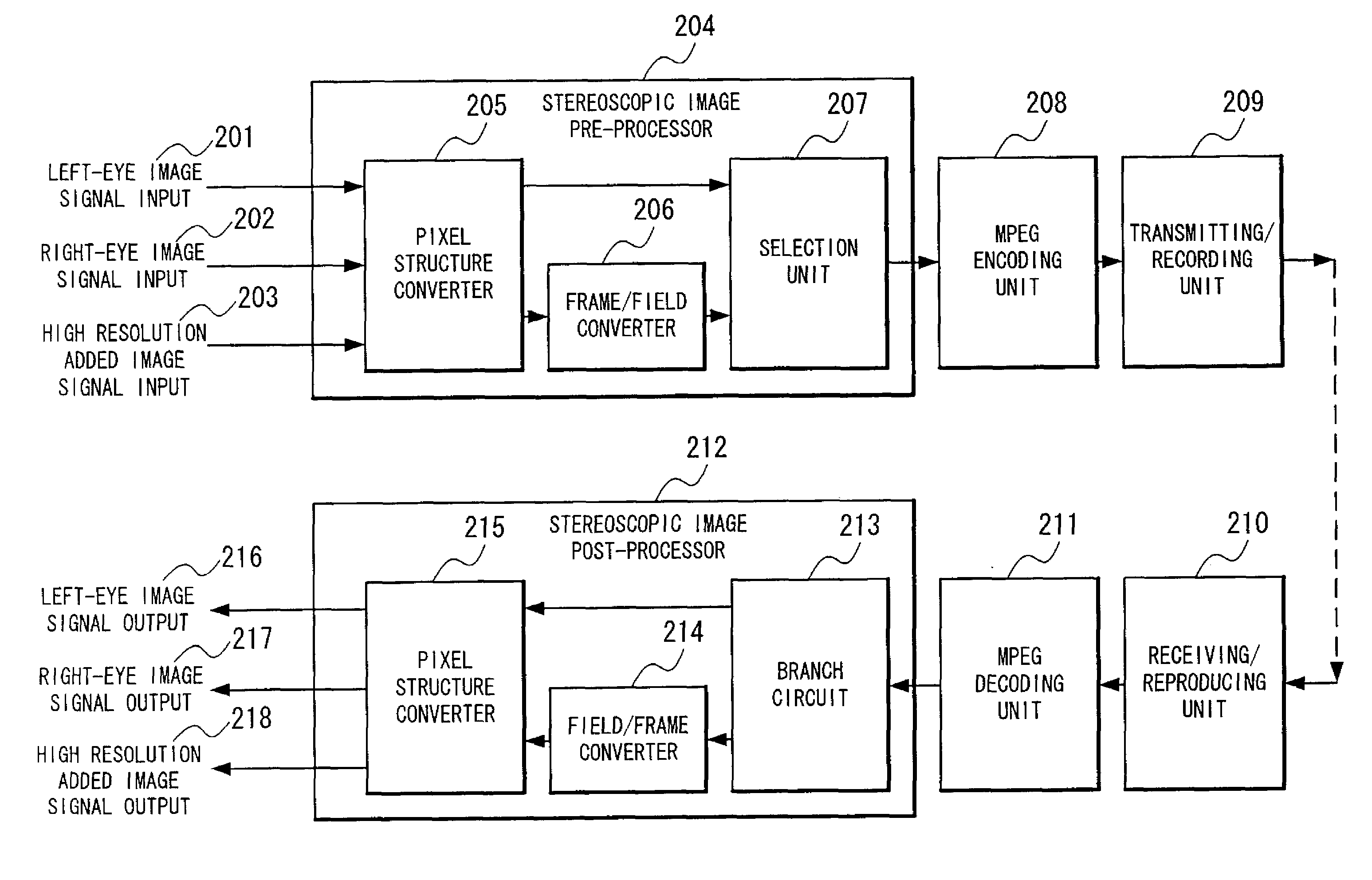
[0078]A stereoscopic image 301 consists of left-eye images (◯) 302 and right-eye images (×) 303 and the left-eye image 302 and the right-eye image 303 respectively correspond to the left-eye image signal input 101 and the right-eye image signal input 102 in FIG. 1. They are arranged on a display as illustrated by 301. Namely, the left-eye images and the right-eye images are arranged alternatively in every other vertical line. The example of FIG. 3 shows the sum of 352 pixels×288 lines including the left-eye images of 176 pixels×288 lines and the right-eye images of 176 pixels×288 lines.

[0079]The stereoscopic image 301 is converted into a first conversion image 304 by the pixel structure converter 104. Namely, the left-eye images of 176 pixels×288 lines are arranged in odd lines by only parallel movement and the right-...


PUM


Abstract

A left-eye image signal and a right-eye image signal are supplied to a pixel structure converter of a stereoscopic image pre-processor, and multiplexed, so to form one image, an interlace image is formed by a frame / field converter, encoded in an MPEG format by an MPEG encoding unit, stored into a storage and transmitted outward by a transmitting / recording unit. The encoded stereoscopic image signal received from the outward and reproduced from the storage is decoded by am MPEG decoding unit after going through a receiving / reproducing unit, the interlace image is reproduced, returned to the frame image by a field / frame converter of a stereoscopic image post-processor, and reproduced as the left-eye image signal and the right-eye image signal and output by the pixel structure converter.

Description

BACKGROUND OF THE INVENTION[0001]1. Field of the Invention[0002]The present invention relates to a stereoscopic image encoding device for efficiently encoding and transmitting image data including a stereoscopic image, a stereoscopic image and plane image, a stereoscopic image and high resolution plane image, and a stereoscopic image and high resolution added image, and a stereoscopic image decoding device for efficiently receiving and decoding the image data.[0003]2. Description of the Related Art[0004]As the conventional encoding method of a stereoscopic image signal, patented is, for example, “Stereoscopic Video Image Transmission Method and System” disclosed in Japanese Patent Laid-Open (kokai) No. Heisei 11-018111.[0005]The constitutional example of this invention is shown in FIG. 20.[0006]A stereoscopic image 2001 is formed by left-eye images (◯) 2002 and right-eye images (×) 2003. They are disposed on a display as shown by 2001. Namely, left-eye images and right-eye images ar...

Claims


Application Information

Patent Timeline
Patent Type & Authority Applications(United States)
IPC IPC(8): G06K9/36G06T9/00H04N13/00H04N19/00H04N19/112H04N19/137H04N19/176H04N19/503H04N19/61H04N19/625H04N19/85H04N19/91
CPCH04N19/597H04N19/112H04N19/61
Inventor ITOI, SATOSHITAKANASHI, NOBUAKI
Owner NEC CORP
Why Eureka
Try Eureka