Convertible gas turbine engine

a gas turbine engine and conversion technology, applied in combination engines, machines/engines, mechanical equipment, etc., can solve the problems of low power subsonic flight efficiency, high cost, and low power of low-power subsonic operation, and achieve the effect of constant core pressure ratio and variable bypass ratio of engin

Inactive Publication Date: 2008-07-03
GENERAL ELECTRIC CO
View PDF11 Cites 59 Cited by
  • Summary
  • Abstract
  • Description
  • Claims
  • Application Information

AI Technical Summary

Problems solved by technology

Future mixed mission morphing aircraft as well as more conventional mixed mission capable military systems that have a high value of take-off thrust / take-off gross weight, i.e., a thrust loading in the 0.8-1.2 category, present many challenges to the propulsion system.
They need efficient propulsion operation at diverse flight speeds, altitudes, and particularly at low power settings where conventional engines operate at inefficient off-design conditions both in terms of uninstalled performance and, to an even greater degree, fully installed performance that includes the impact of spillage drag losses associated with supersonic inlets.
In particular, the fan pressure ratio and related bypass ratio selection needed to obtain a reasonably sized engine capable of developing the thrusts needed for combat maneuvers and supersonic operation are non-optimum for efficient low power subsonic flight.
Basic uninstalled subsonic engine performance is compromised and fully installed performance suffers even more due to the inlet / engine flow mismatch that occurs at reduced power settings.

Method used


Image

  • Convertible gas turbine engine
  • Convertible gas turbine engine
  • Convertible gas turbine engine

Examples


Embodiment Construction

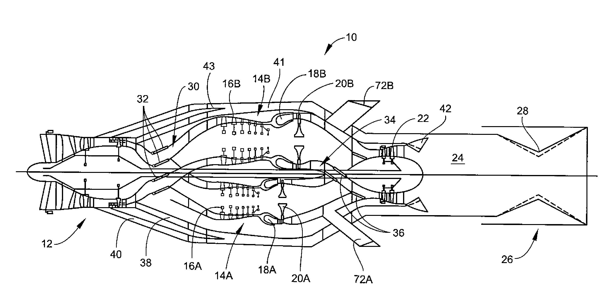
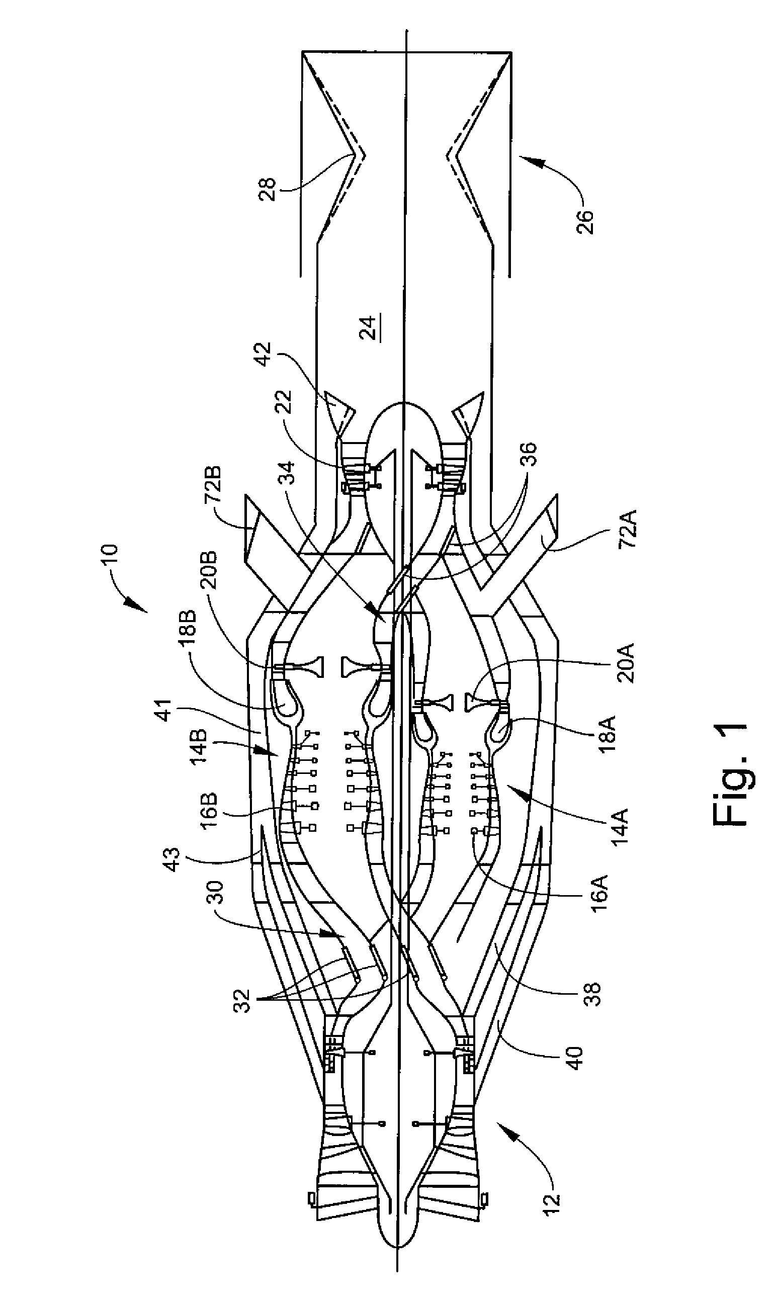
[0015]Referring to the drawings wherein identical reference numerals denote the same elements throughout the various views, FIG. 1 illustrates a portion of an exemplary convertible gas turbine engine, generally designated 10. The engine 10 has a fan 12, a first core 14A including a first compressor 16A, first combustor 18A, and first high pressure turbine 20A, and a second core 14B which includes a second compressor 16B, second combustor 18B, and second high pressure turbine 20B. The fan 12 is driven by a low pressure turbine 22 disposed downstream of the cores 14A and 14B. The cores 14A and 14B can optionally have the same design pressure ratios, but have different design flow rates, with the second core 14B having a higher design and maximum flow. An exhaust duct 24 is disposed downstream of the low pressure turbine 22, and a convergent-divergent exhaust nozzle 26 is disposed downstream of the exhaust duct 24. The throat 28 of the exhaust nozzle 26 may have a variable area “A8”, a...


PUM


Abstract

A gas turbine engine includes a turbomachinery core operable to generate a flow of pressurized combustion gases at a variable flow rate, while maintaining a substantially constant core pressure ratio; a rotating fan disposed upstream of the core, the fan adapted to extract energy from the core and generate a first flow of air which is compressed at a first pressure ratio; and at least a first bypass duct surrounding the core downstream of the fan adapted to selectively receive at least a first selected portion of the first flow which is compressed at a second pressure ratio lower than the first pressure ratio, and to bypass the first selected portion around the core, thereby varying a bypass ratio of the engine. The fan is adapted to maintain a flow rate of the first flow substantially constant, independent of the bypass ratio.

Description

BACKGROUND OF THE INVENTION[0001]This invention relates generally to gas turbine engines and more particularly to a turbofan engine in which the fan flow can be modulated independent of the fan speed.[0002]Future mixed mission morphing aircraft as well as more conventional mixed mission capable military systems that have a high value of take-off thrust / take-off gross weight, i.e., a thrust loading in the 0.8-1.2 category, present many challenges to the propulsion system. They need efficient propulsion operation at diverse flight speeds, altitudes, and particularly at low power settings where conventional engines operate at inefficient off-design conditions both in terms of uninstalled performance and, to an even greater degree, fully installed performance that includes the impact of spillage drag losses associated with supersonic inlets.[0003]When defining a conventional engine cycle and configuration for a mixed mission application, compromises have to be made in the selection of f...

Claims


Application Information

Patent Timeline
Patent Type & Authority Applications(United States)
IPC IPC(8): F02K3/02
CPCF02K3/075F02K3/06
Inventor JOHNSON, JAMES EDWARD
Owner GENERAL ELECTRIC CO
Why Eureka
Try Eureka