System and method for detecting fluid in terminal block area of field device

a field device and terminal block technology, applied in the field of monitoring the condition of field devices, can solve the problems of field devices often located in physically challenging environments, field devices to fail, difficult and time-consuming,

Active Publication Date: 2008-07-03
ROSEMOUNT INC
View PDF11 Cites 29 Cited by
  • Summary
  • Abstract
  • Description
  • Claims
  • Application Information

AI Technical Summary

Problems solved by technology

Field devices are often located in physically challenging environments, with one potential problem being the collection of fluid within the terminal block area of the field device.
The presence of fluid within the terminal block area can have a corrosive effect on the terminals and wires located within the terminal block area, ultimately causing the field device to fail.
It is difficult and time-consuming, however, to periodically inspect each field device.

Method used


Image

  • System and method for detecting fluid in terminal block area of field device
  • System and method for detecting fluid in terminal block area of field device
  • System and method for detecting fluid in terminal block area of field device

Examples


Embodiment Construction

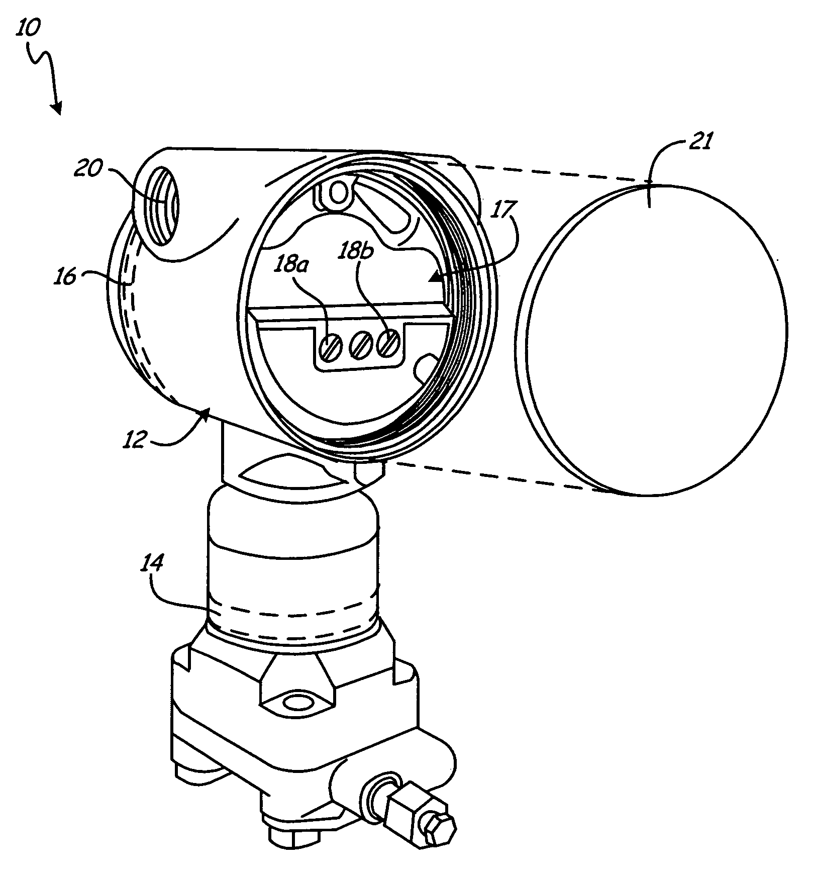
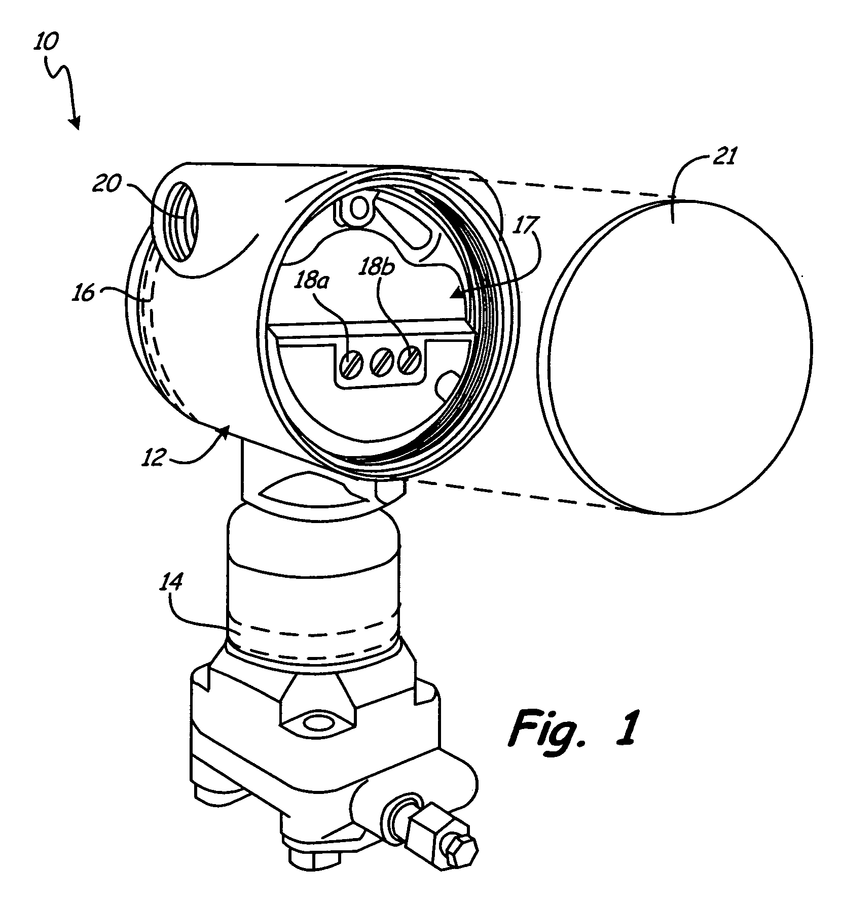
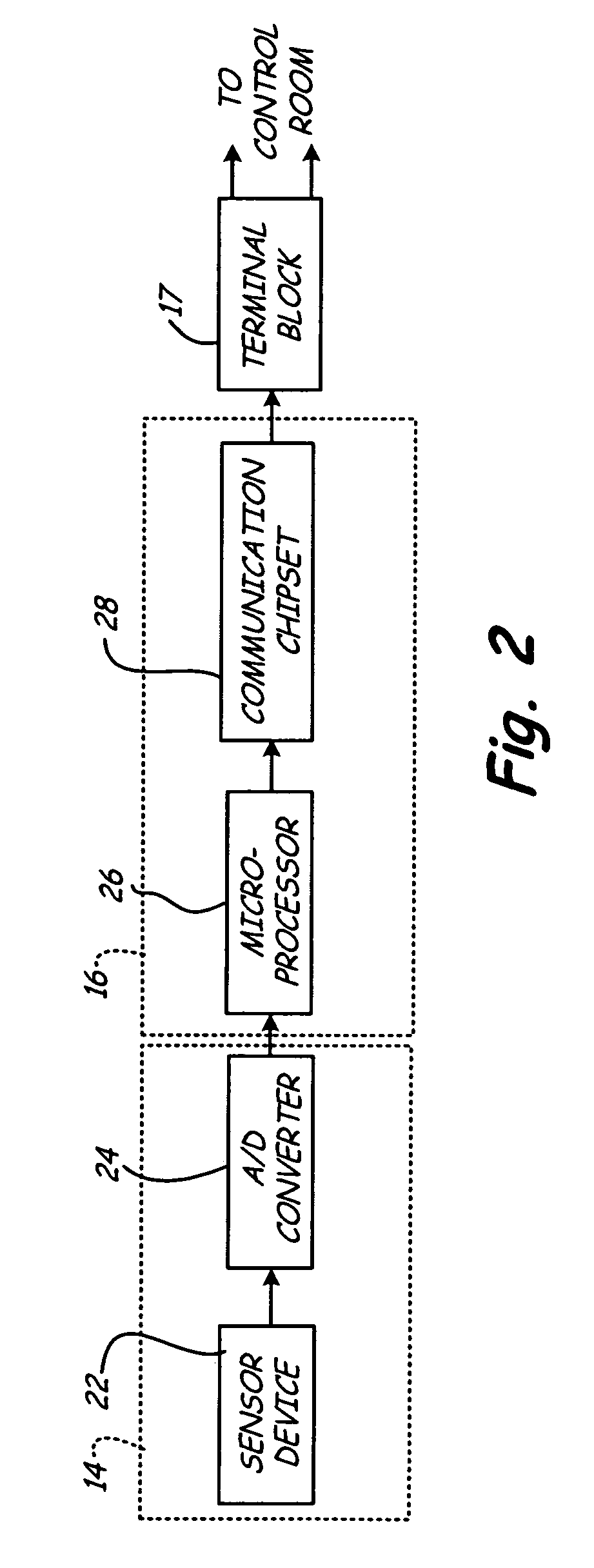
[0013]FIG. 1 illustrates field device 10, which includes housing 12, sensor board 14, circuit board 16, and terminal block 17 (which includes at least two terminals labeled 18a and 18b). Sensor board 14 measures a process variable (e.g. pressure, temperature, flow, etc.) and converts the measured process variable to an electronic signal. Circuit board 16 converts the signal provided by sensor board 14 to a signal that can be communicated to a control room, using either the traditional 4-20 mA analog communication technique, or some form of digital communication protocol (e.g., HART). Wiring from the control room enters field device 10 through field conduit port 20, and is connected to terminals 18a and 18b within terminal block 17.

[0014]Terminal block 17 includes threads that allow a cover 21 to be placed over terminal block 17. Ideally, housing 12 and cover 21 act to protect terminals 18a and 18b from environmental factors, such as fluid accumulation in terminal block 17. Despite t...


PUM


Abstract

A field device detects the presence of fluid in the terminal block area of the field device by generating an alternating current (AC) test current signal and measuring the amplitude of the resulting AC voltage signal. The field device includes a first terminal and a second terminal adapted for connection to a control room through a twisted-wire pair current loop. Impedance of the current loop is increased by the presence of fluid between the first terminal and the second terminal. By providing an AC test current signal to the control loop and measuring a resulting AC voltage magnitude, the impedance of the control loop can be determined. Increased impedance in the control loop indicates the presence of water in the terminal block.

Description

BACKGROUND OF THE INVENTION[0001]The present invention relates to monitoring the condition of field devices. Specifically, the invention relates to a system for detecting the presence of fluids in the field devices.[0002]In many industrial settings, control systems are used to monitor and control inventories, processes, and the like. A typical control system includes a centralized control room and a number of field devices geographically removed from the control room. The field devices communicate process data to the control room using either analog or digital communication means.[0003]Traditionally, analog field devices have been connected to the control room by two-wire twisted-pair current loops, with each field device connected to the control room by a single two-wire twisted pair loop. Located within the field device housing are terminals for connecting the twisted-pair current loops to circuitry within the field device. This region is referred to as the terminal block area of ...

Claims


Application Information

Patent Timeline
Patent Type & Authority Applications(United States)
IPC IPC(8): G01F23/00
CPCG01M3/16H05K7/1462G01M3/40
Inventor WEHRS, DAVID L.
Owner ROSEMOUNT INC
Why Eureka
Try Eureka