Oral airways that facilitate tracheal intubation

a technology of oral airways and trachea, applied in the field of oral airways, can solve the problems of cumbersome difficult difficult removal of oral airways, and achieve the effects of facilitating fiber optic scoping process, and reducing the risk of infection

Active Publication Date: 2008-07-03
AMY ISENBERG
View PDF44 Cites 25 Cited by
  • Summary
  • Abstract
  • Description
  • Claims
  • Application Information

AI Technical Summary

Benefits of technology

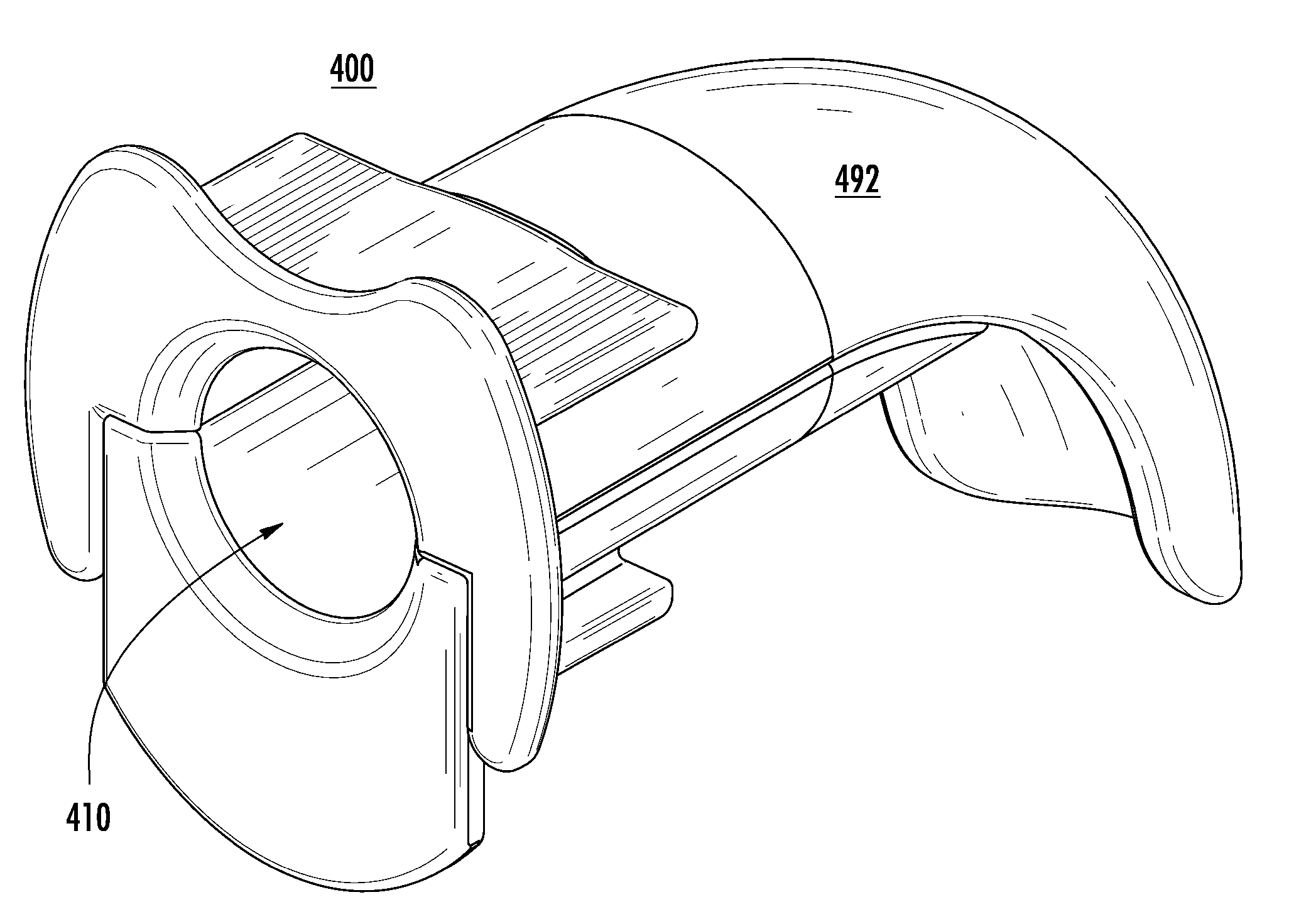
[0014]In an aspect of the invention, an oral airway includes first and second components that are removably coupled together to define a conduit configured to receive therethrough a fiber-optic scope or an endotracheal tube for intubation of the trachea of a patient. Furthermore, the first and second components are configured to be decoupled and independently removed from a patient's mouth without disrupting an endotracheal tube that has been received through the conduit for tracheal intubation.
[0047]In a feature of this aspect, the first and second components, when coupled together, define a wide, flat lingual surface that allows for stability of the oral airway and forward depression of the tongue when placed within a patient's mouth.

Problems solved by technology

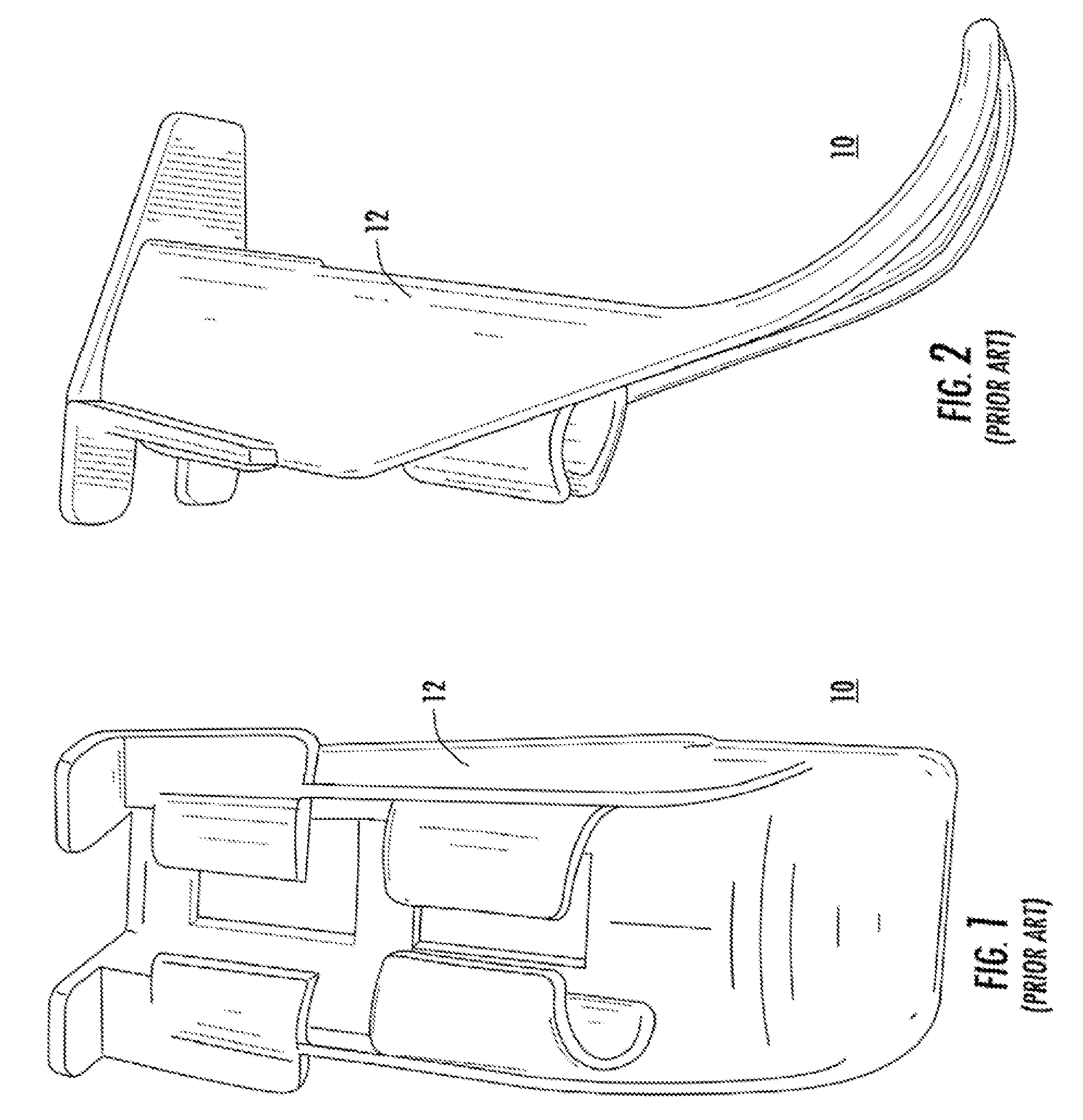
The oral airway 10 also has been found to be very difficult to remove without disrupting placement of an endotracheal tube after the endotracheal tube has been properly positioned with respect to the trachea.
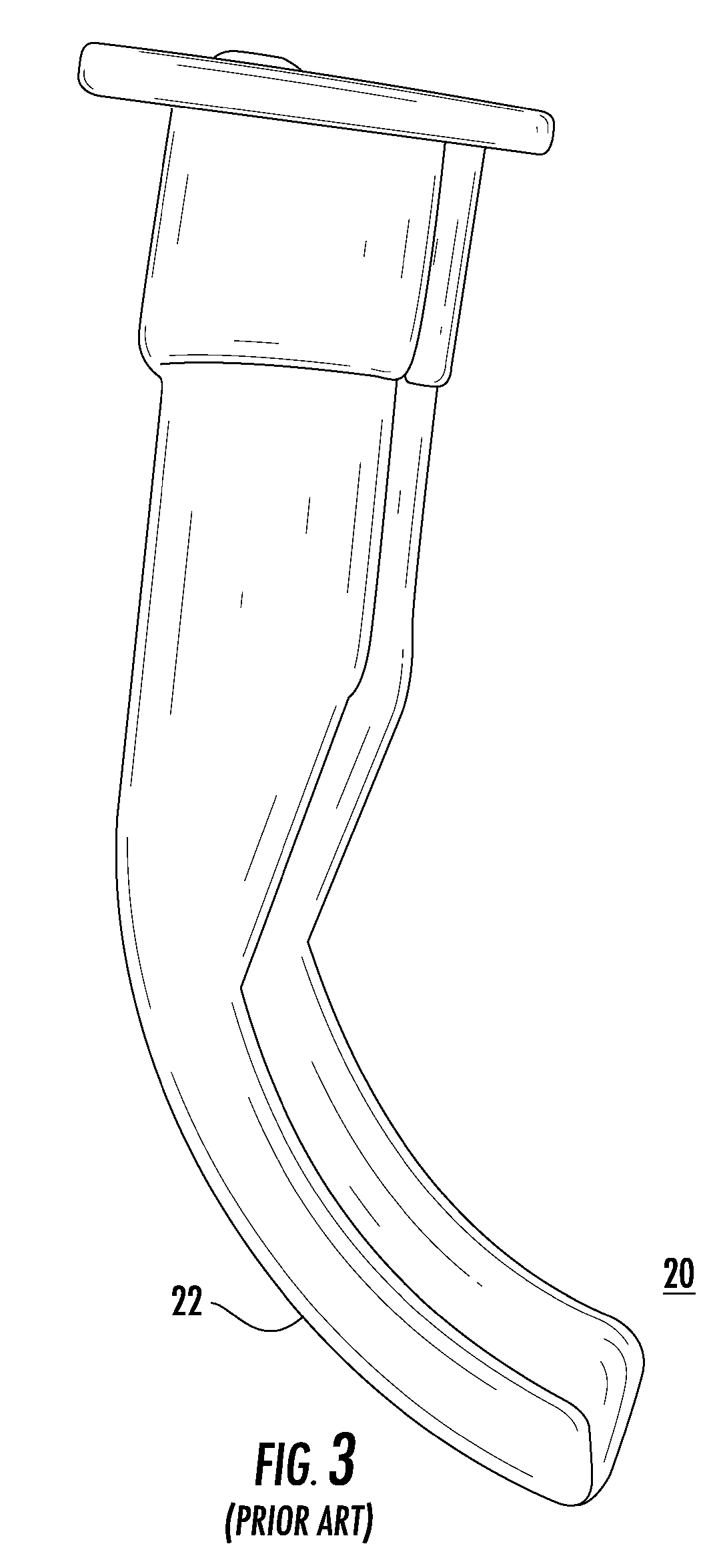
Unfortunately, the oral airway 20 has been found to be very narrow and to wobble in a patient's mouth, thereby making the fiber-optic scoping process difficult.
The oral airway 20 also has been found to be cumbersome to remove without disrupting placement of an endotracheal tube after the endotracheal tube has been properly positioned with respect to the trachea.
Unfortunately, the oral airway 30 has been found to be very narrow and unstable and to include a posterior curve that tends to direct a fiber-optic scope and endotracheal tube posteriorly toward the esophagus instead of anteriorly toward the trachea.

Method used


Image

  • Oral airways that facilitate tracheal intubation
  • Oral airways that facilitate tracheal intubation
  • Oral airways that facilitate tracheal intubation

Examples


Embodiment Construction

[0095]As a preliminary matter, it will readily be understood by one having ordinary skill in the relevant art (“Ordinary Artisan”) that the invention has broad utility and application. Furthermore, any embodiment discussed and identified as being “preferred” is considered to be part of a best mode contemplated for carrying out the invention. Other embodiments also may be discussed for additional illustrative purposes in providing a full and enabling disclosure of the invention. Moreover, many embodiments, such as adaptations, variations, modifications, and equivalent arrangements, will be implicitly disclosed by the embodiments described herein and fall within the scope of the invention.

[0096]Accordingly, while the invention is described herein in detail in relation to one or more embodiments, it is to be understood that this disclosure is illustrative and exemplary of the invention, and is made merely for the purposes of providing a full and enabling disclosure of the invention. Th...


PUM


Abstract

An oral airway includes a first component having a first guiding surface and a second component having a second guiding surface. The first component and the second component are adapted to be removably coupled together such that the first guiding surface and the second guiding surface collectively define and encompass an interior passage through the oral airway that is dimensioned to direct, for example, a fiber-optic scope or an endotracheal tube extending through the interior passage for tracheal intubation. The first and second components are configured to be decoupled and independently removed from a patient's mouth without disrupting an endotracheal tube that has been extended through the conduit for tracheal intubation. The first and second components may be maintained in coupled disposition by an interlocking mechanical structure. The first and second components also may be maintained in coupled disposition by magnetism.

Description

CROSS-REFERENCE TO RELATED APPLICATION[0001]The present application is a U.S. nonprovisional patent application of, and claims priority under 35 U.S.C. § 119(e) to, U.S. provisional patent application Ser. No. 60 / 883,116, filed Jan. 2, 2007, which provisional patent application is incorporated by reference herein.COPYRIGHT STATEMENT[0002]All of the material in this patent document is subject to copyright protection under the copyright laws of the United States and other countries. The copyright owner has no objection to the facsimile reproduction by anyone of the patent document or the patent disclosure, as it appears in official governmental records but, otherwise, all other copyright rights whatsoever are reserved.BACKGROUND OF THE INVENTION[0003]The invention generally relates to oral airways and, in particular to oral airways that facilitate fiber-optic intubation of the trachea.[0004]Oral airways are well known. Generally, an oral airway is a device used in anesthesia to mainta...

Claims


Application Information

Patent Timeline
Patent Type & Authority Applications(United States)
IPC IPC(8): A61M16/04
CPCA61M16/0488A61M16/049A61M16/0493A61M16/0495A61M2210/1028A61B1/00154A61B1/00165A61B1/2673A61M2205/02A61B1/00105
Inventor ISENBERG, AMYHOY, CHRIS
Owner AMY ISENBERG
Why Eureka
Try Eureka