Intubation device and method of use

a technology of intubation device and tube, which is applied in the field of intubation tube, can solve the problems of irreversible brain damage and death, difficult procedure of placement of endotracheal tube, training and knowledge,

Inactive Publication Date: 2006-09-21
RADLYN LLC
View PDF38 Cites 19 Cited by
  • Summary
  • Abstract
  • Description
  • Claims
  • Application Information

AI Technical Summary

Benefits of technology

[0053]FIG. 10 is a partial view of another preferred embodiment of the invention showing the forward open end of the endotra

Problems solved by technology

Often these emergency evaluations are performed by individuals having inadequate training and knowledge in airway management.
The inability to secure an airway and provide a route of ventilation in someone whose airway is threatened, compromised, or obstructed can quickly result in irreversible brain damage and death.
Placement of an endotracheal tube, however, is often found to be a difficult procedure, even by well-trained, experienced personnel.
This difficulty can be attributed to the anatomical variations or the encountered situation in which the airway needs to be secured.
Further, during the process of placing an endotracheal tube into the trachea of a patient, it is not uncommon that only minimal visualization of the laryngeal anatomy can be obtained thereby increasing the chances that esophageal intubation can occur.
Endotracheal tubes are generally formed of soft, pliable plastic materials that increase in plasticity in the warm humidified air encountered when passing through the hypopharynx, thereby increasing the difficulty of placing an endotracheal tube through the glottic opening even under the most optimal visualization.
Making the endotracheal tube out of a stiffer material, however, is not an acceptable alternative because it would cause excessive trauma to the nasal or throat tissue as the laryngeal and surrounding mucosa is extremely sensitiv

Method used


Image

  • Intubation device and method of use
  • Intubation device and method of use
  • Intubation device and method of use

Examples


Embodiment Construction

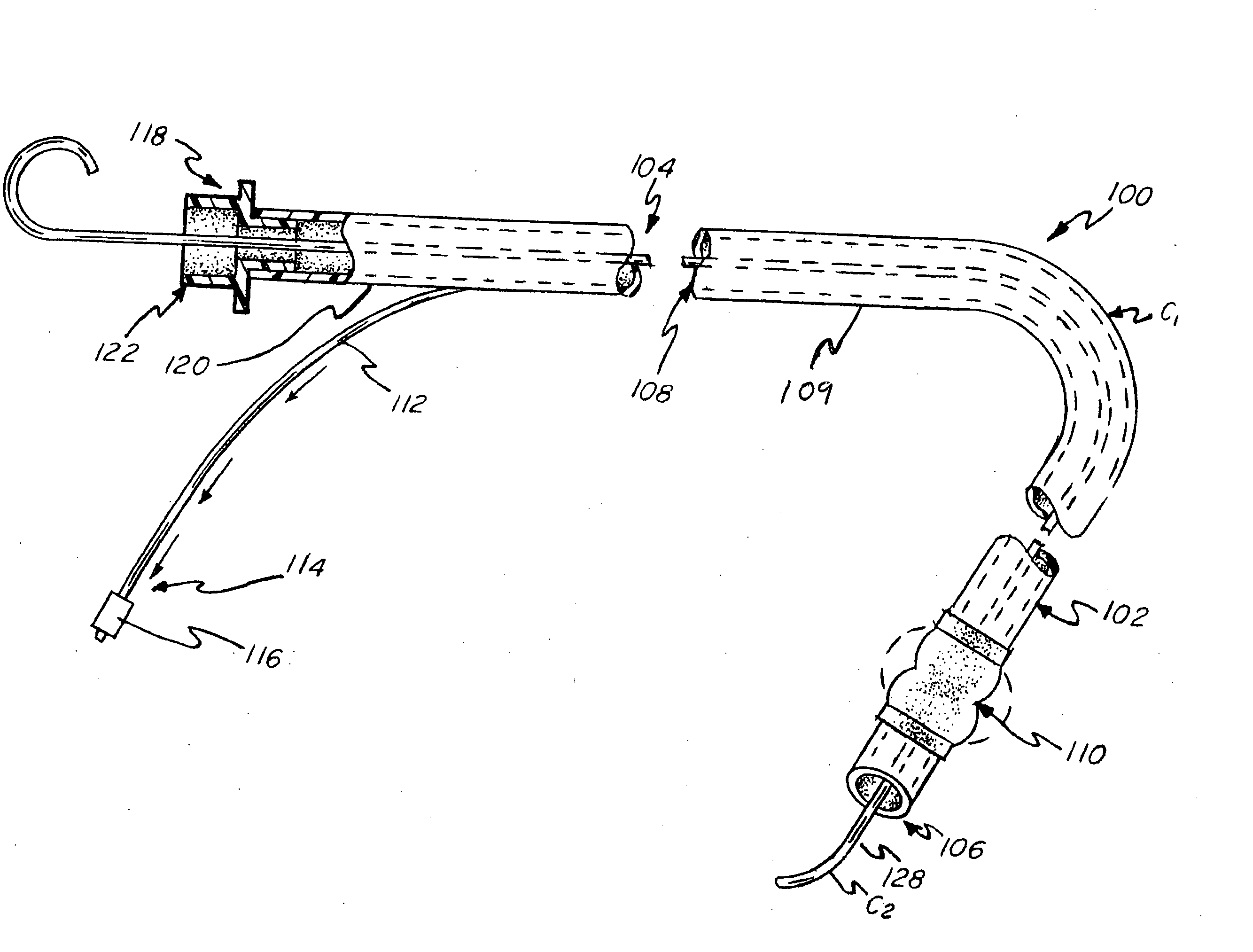
[0068] The present invention relates to a method of performing endotracheal intubation and a new and novel intubation device for performing the method. In describing the preferred embodiments of the invention illustrated in the drawings, specific terminology will be resorted to for the sake of clarity. However, the invention is not intended to be limited to the specific terms so selected, and it is to be understood that each specific term includes all technical equivalents that operate in a similar manner to accomplish a similar purpose.

[0069] For purposes of the description of the present invention, the terms “distal”, “forward” and “forwardly” are intended to refer to the direction towards the patient receiving the intubation device, whereas the terms “proximal”, “rear” and “rearwardly” are intended to refer to the direction away from the patient receiving the intubation device.

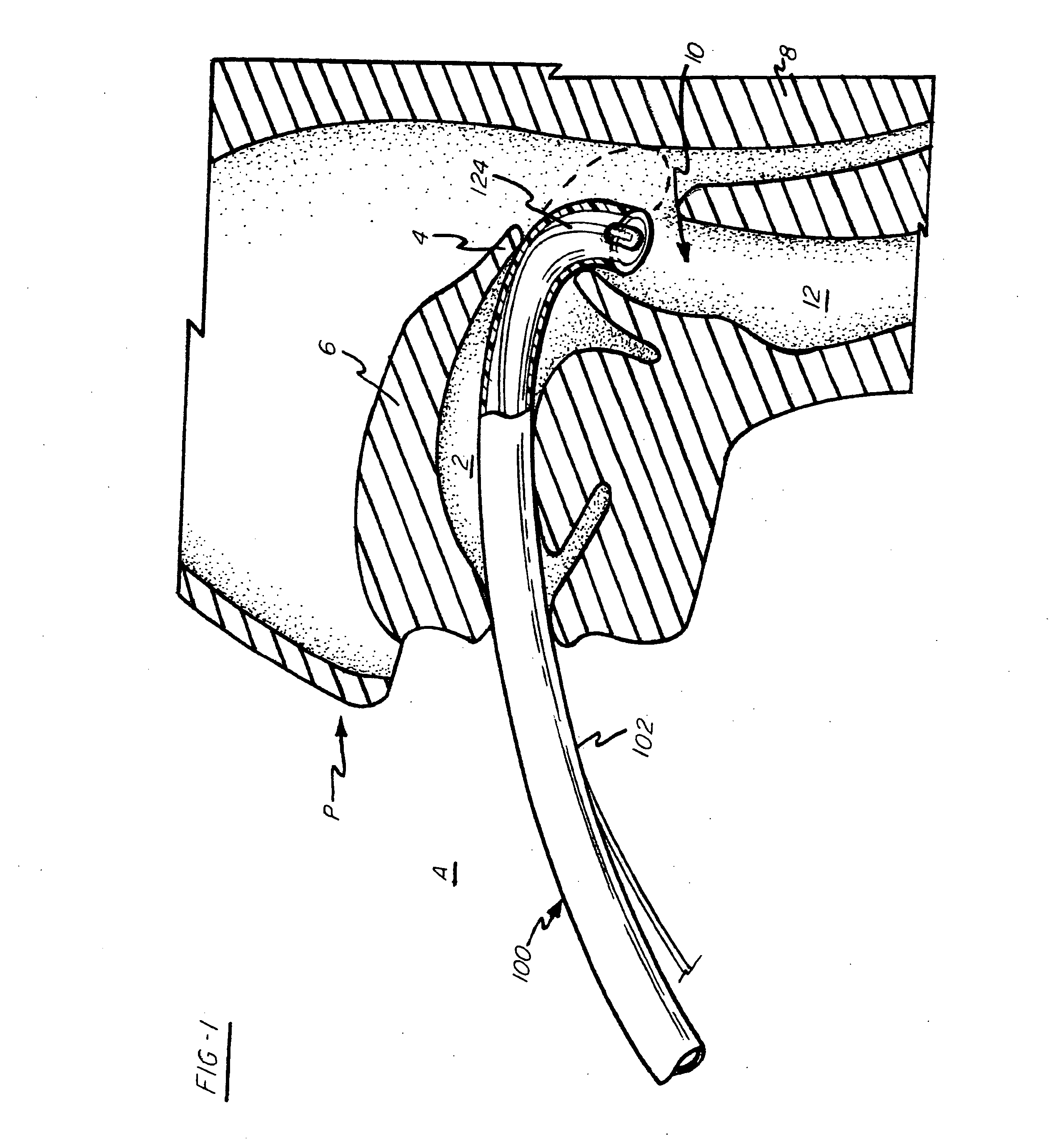
[0070] Referring to FIG. 1, a partial cross-section of a patient P is shown illustrating the mouth 2, ...


PUM


Abstract

The present invention is a method of performing endotracheal intubation and a new and novel intubation device for performing the method. In an exemplary embodiment of the invention, the intubation device comprises an endotracheal tube having a forward open end and a rearward open end and an inner bore there between. A stylet is telescopingly positioned within the inner bore and extends outwardly from the forward open end and includes a longitudinally extending soft and flexible guide portion. A distal stylet cuff may be inflated to provide a smooth transition from the guide portion to the endotracheal tube, and a proximal unidirectional end cap may engage a proximal connector of the endotracheal tube and cooperate with the cuff to seat the stylet within the endotracheal tube for intubation as a unitary whole.

Description

RELATED APPLICATIONS [0001] This is a continuation-in-part application of a prior filed and currently pending application having Ser. No. 10 / 455,929 and a filing date of Jun. 6, 2003.BACKGROUND OF THE INVENTION [0002] 1. Incorporation by Reference [0003] Applicant hereby incorporates herein by reference any and all U.S. patents and U.S. patent applications cited or referred to in this application. [0004] 2. Field of the Invention [0005] Aspects of this invention relate to an intubation tube and more particularly, to a new and improved intubation device having a stylet for use in placing an endotracheal tube into the trachea of a patient. [0006] 3. Description of Related Art [0007] Intubation devices, such as oral-endotracheal tubes, are utilized in a wide variety of medical situations to provide an unobstructed conduit to a patient's trachea in which oxygen, medications and therapies can be passed. In most situations in which medical attention is needed, medical personnel will first...

Claims


Application Information

Patent Timeline
IPC IPC(8): A62B9/06A61M16/00A61MA61M5/00A61M5/178A61M11/00
CPCA61M16/04A61M16/0434A61M16/0463A61M16/0488A61M16/0418A61M16/0427A61M16/0443A61M16/0445A61M16/0486
Inventor NELSON, LINDSEY A.MONGEON, DOUGLAS R.
Owner RADLYN LLC
Why Eureka
Try Eureka