
Method, System, and Apparatus of Cutting Earthen Formations and the like

a technology of earthen formations and cutting methods, applied in earth drilling and mining, drill bits, construction, etc., can solve problems such as time and money-consuming, failure rate of entire drill bit, and failure of bit failures

Inactive Publication Date: 2008-07-03
PDTI HLDG
View PDF38 Cites 35 Cited by
  • Summary
  • Abstract
  • Description
  • Claims
  • Application Information

AI Technical Summary

Benefits of technology

[0010]In one aspect of the present invention, a cutter element is provided for use on a rotary drill bit of a drilling string to cut earthen formations and the like. The cutter element includes a cutting portion formed from cutting material (e.g., polycrystalline diamond) adapted to cut into the earthen formation, and a substrate positioned adjacent the cutting portion. The cutting portion and the substrate form a body (e.g., substantially rod shaped) having a substantially planar front face, a longitudinal axis extending centrally through the front face and the substrate, and a circumferential surface exten

Problems solved by technology

Fracture is typically a result of a combination of applied cutting loads and stresses associated with the cutter geometry and stresses residual to the high pressure / high temperature manufacturing process.
Such exposed substrates have high rates of failure and therefore may lead to the progressive failure of the entire drill bit.
Bit failures cost time and money through reduced performance and additional trip time.

Method used


Image

  • Method, System, and Apparatus of Cutting Earthen Formations and the like
  • Method, System, and Apparatus of Cutting Earthen Formations and the like
  • Method, System, and Apparatus of Cutting Earthen Formations and the like

Examples


Embodiment Construction

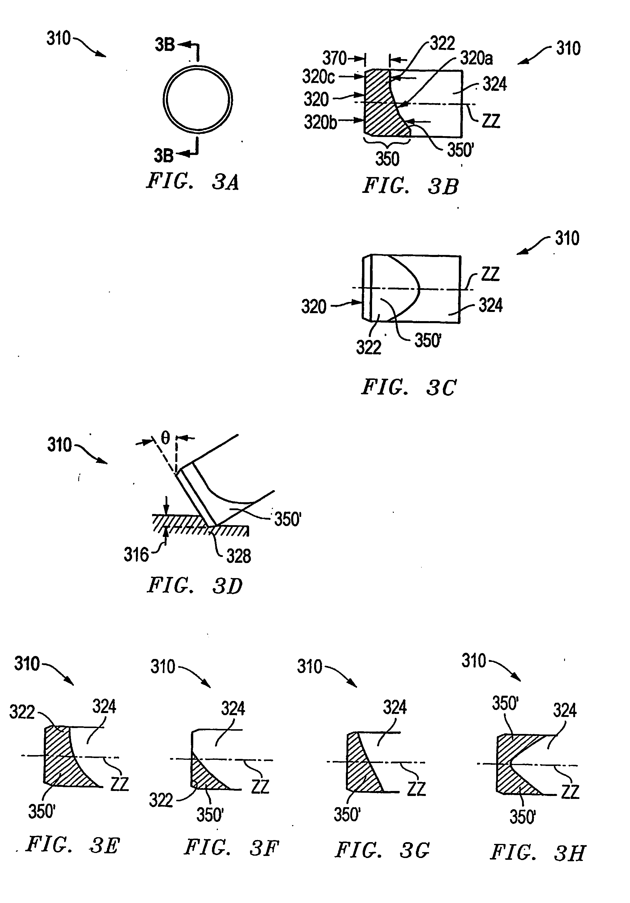
[0024]FIGS. 3A, 3B, and 3C provide front, longitudinal (vertical) cross-sectional, and bottom views, respectively of a cutting element or cutter 310 according to the present invention. The longitudinal axis ZZ may be described as dividing the cross-section into two halves.

[0025]The cutter 310 has a front or cutting face 320 outlined by a circumference or peripheral edge 320a (which may be a chamfered, beveled, or straight edge), and the longitudinal axis, ZZ, extending from the center of the cutting face 320 and generally normal thereto. The cutter 310 includes a substantially forward cutting portion 322 that is preferably comprised of polycrystalline diamond material and thus, referred to as a diamond table. In other embodiments, the material for the cutting portion may be tungsten carbide, cubic boron nitride, or other commonly used materials. The cutter 310 further includes a substantially rearward portion provided by a substrate 324. The substrate 324 is preferably formed from t...


PUM


Abstract

A cutter element is provided for use on a rotary drill bit of a drilling string to cut earthen formation and the like. The cutter element includes a cutting portion formed from cutting material adapted to cut into the earthen formation, and a substrate positioned adjacent the cutting portion. The cutting portion and the substrate form a body having a substantially planar front face, a longitudinal axis extending centrally through the front face and the substrate, and a circumferential surface extending inwardly form the front face and spaced outwardly from the longitudinal axis. The cutting portion includes a cutting face that provides at least a portion of the front face. The cutting portion extends longitudinally inward from the front face to a back surface engaging or inter-facing the substrate. Thus, a distinct, longitudinally extending volume of cutting material is provided and includes a predesignated portion of the circumferential surface that extends from the cutting face to the back surface, the circumferential surface portion being predesignated for wearing contact with the earthen formation.

Description

[0001]The present application claims the benefit of the filing date of U.S. Provisional Application Ser. No. 60 / 473,832, filed May 27, 2003 (pending) (hereby incorporated by reference for all purposes and made a part of the present disclosure).BACKGROUND OF THE INVENTION[0002]1. Field of the Invention[0003]The present invention relates to methods, systems, and / or apparatus for cutting earthen formations that may be above ground or subterranean, and, more particularly, but not by way of limitation, to methods of and apparatus for cutting earthen formations for various applications such as oil, gas, and geothermal production, in addition to excavations including tunnels, pipe chases, foundation piers, building stone, quarried rock, etc.[0004]2. Description of the Related Art[0005]The prior art is replete with designs for cutting elements or cutters secured on a drill bit and utilized in the drilling of well bores or the cutting of formations for the construction of tunnels and other s...

Claims


Application Information

Patent Timeline
IPC IPC(8): E21B10/36E21BE21B10/46E21B10/567E21B10/573
CPCE21B10/573E21B10/567
Inventor TIBBITTS, GORDON ALLEN
Owner PDTI HLDG
Features
  • Generate Ideas
  • Intellectual Property
  • Life Sciences
  • Materials
  • Tech Scout
  • Unparalleled Data Quality
  • Higher Quality Content
  • 60% Fewer Hallucinations
Learn More