Integrated infusion management system

a management system and infusion technology, applied in the field of support stands, can solve the problems of stability and/or storage deficiencies of conventional iv pole systems, and achieve the effects of convenient and easy use, increased stability and resistance to tipping

Active Publication Date: 2008-07-03
FIREFLY MEDICAL
View PDF32 Cites 34 Cited by
  • Summary
  • Abstract
  • Description
  • Claims
  • Application Information

AI Technical Summary

Benefits of technology

Conventional IV pole systems have limitations when it comes to stability and storage capacity. However, this patent introduces new designs that offer improved stability and resistant against tilting, regardless of usage condition. Additionally, these systems can be easily stored in a compact way and used on different types of medical equipment. They also allow for better patient mobility and ease of handling, making them ideal for healthcare settings where there may be many other medical devices present. Overall, this innovation offers greater functionality and design appeal than conventional IV poles.

Problems solved by technology

The technical problem presented in this patent text is the lack of stability and ease of use for existing IV poles used in medical facilities. Current IV poles tend to be unreliable, heavy, easy to get stuck to surfaces, and take up too much space when not in use. Additionally, these poles fail to provide effective mobility assistance to patients who want to make their way through a facility without getting lost or becoming tired.

Method used


Image

  • Integrated infusion management system
  • Integrated infusion management system
  • Integrated infusion management system

Examples


example 1

IMS Geometry

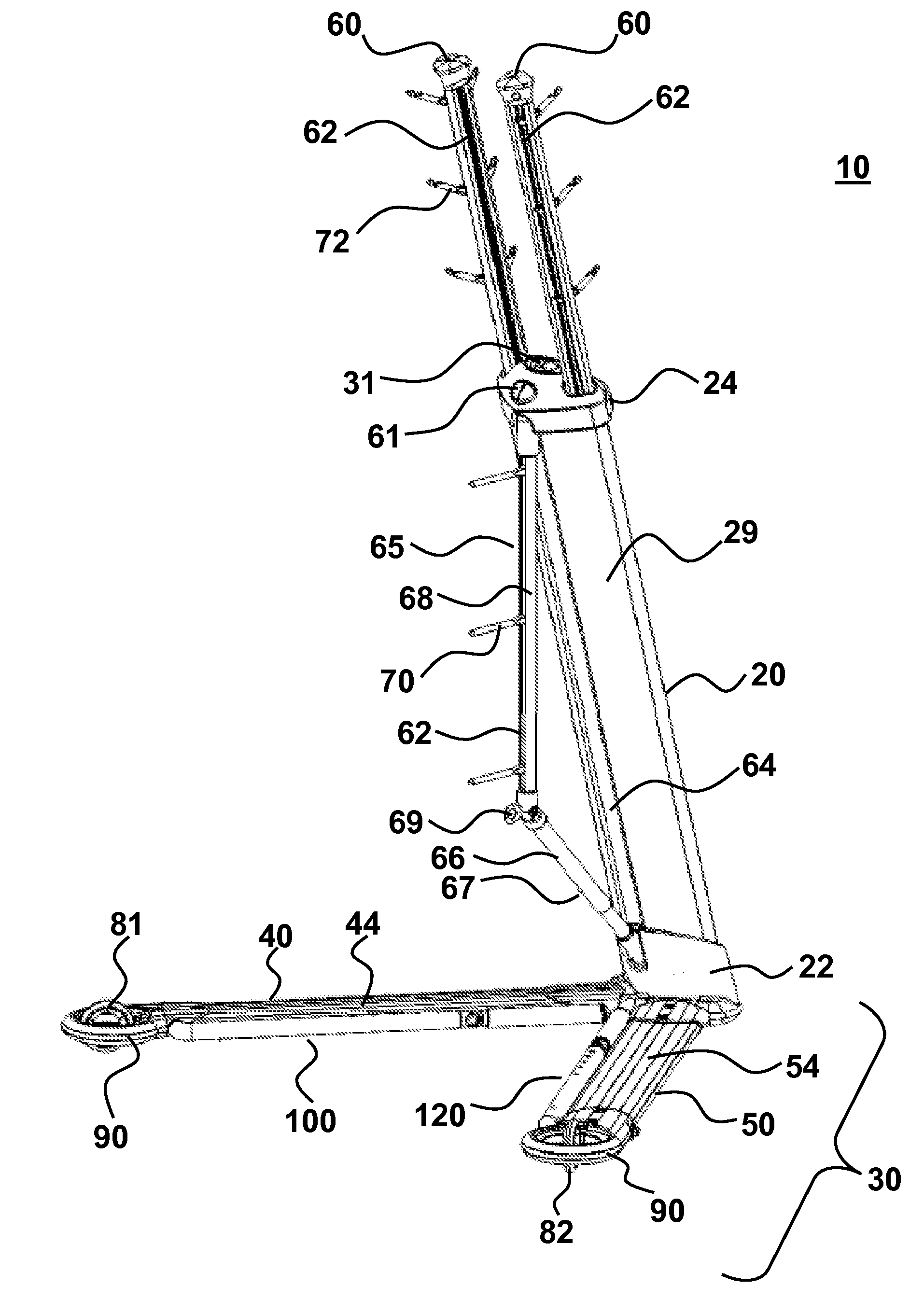
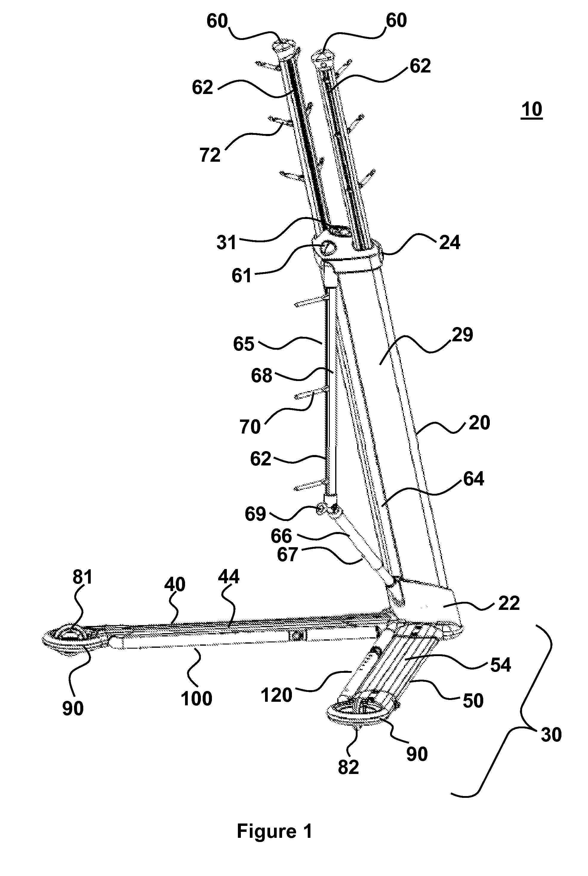
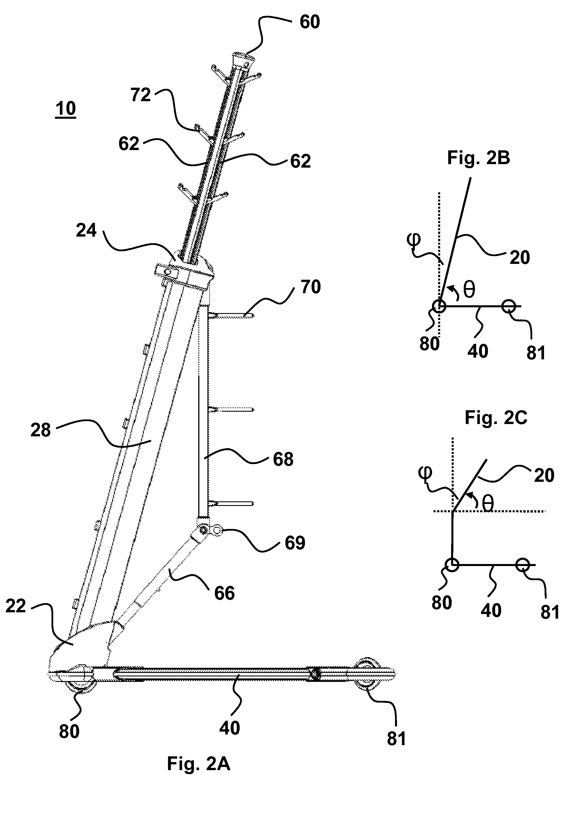
[0108]The infusion management system (IMS) in its most basic configuration comprises a base 30 having a first 40 and second 50 base arm connected to a trunk 20 (FIG. 1). FIGS. 1-6 show an IMS in the base deployed configuration 10. Base arms 40 and 50 are connected to trunk 20 bottom end 22. The trunk 20 has at least an axial portion corresponding to a non-zero angle relative to vertical and an acute angle relative to base arms 40 and 50. This geometry is summarized in FIG. 2B, with the acute angle formed between trunk 20 and base arm 40 (or 50) labeled as E and the non-zero angle relative to vertical labeled as φ. In the exemplified embodiment of FIGS. 1-6 (e.g., three wheels deployed), the wheels 81 and 82 attached to base arms 40 and 50, and wheel 80 attached to trunk bottom 22 form a base footprint 32 that is triangular (e.g., see top and bottom views in FIGS. 3 and 4B). Base footprint 32 refers to the triangle defined by the contact point between each of the three wh...

example 2

IMS Walker / Mobility Assistance

[0117]A useful embodiment of the invention is a system that has mobility arms 100 and 120 deployed such that the system is in a base and walker deployed configuration 12 (FIGS. 7-12). FIGS. 1-6 illustrate base-only deployed configuration 10, and FIGS. 7-12 illustrate a system in a base and walker deployed configuration 12. Mobility arms 100 and 120 are connected to base arm 40 and 50, respectively (FIG. 7). The mobility arm 100 and 120 are each pivotally connected to base arm 40 and 50, respectively, so that the mobility arms are deployable. In the exemplified embodiment this pivot connection 102 is located at the inner surface of each base arm (FIG. 8). The connection can also be at other positions, such as the top surfaces 44 and 54 of the base arms 40 and 50 or outer facing surfaces of base arms. Mobility arms 100 and 120 are capable of locking into a deployed position (FIGS. 7-12) or a stored configuration (FIGS. 1-6) by a handle lock assembly 101 t...

example 3

IMS Storage

[0121]FIGS. 13-18 illustrate the system in its stored configuration 14. In particular, each of the individually deployable components (wheels 81 and 82, base arms 40 and 50, handle grip 106, handle (100, 120, 104, 105), holding arm 60, collapsible support 65, holders 70 and 72) are stored to provide maximum compactness. Wheel 80, is shown deployed and can be used to assist in moving system 14 by rolling it over a surface to or from a storage location or to an area where it is to be deployed.

[0122]The system is able to be compactly stored, while retaining the ability to be quickly and easily deployed by a single person. For example, depressing base lock button 31 allows base arms 40 and 50 to unlock from their stored position (parallel to trunk 20) and into their deployed base configuration. Holding arm lock 61 is depressed to deploy holding arms 60 in a position ready to receive one or more medical components. Folding arm 65 is located within a trunk storage groove 64 in ...


PUM


Abstract

An integrated infusion management system provides for stable support of components attached to the system, even when the system is mobile. The system is optionally a mobility assist or walker for a patient who is attached to any number of medical components. A central trunk connects to a two-sided base that does not interfere with patient motion. The trunk may be angled with respect to vertical and oriented to support medical components in a configuration that is tip-resistant. The system is optionally deployable to facilitate conversion between a compact storage configuration and a stable deployed configuration. In an embodiment, additional deployable features include holding arms for holding various medical components, wheels, mobility arms and handles. Also provided is a novel wheel system with deployable wheels and methods associated with providing compact storage of any one or more of the systems presented herein.

Description


Claims


Application Information

Patent Timeline
Owner FIREFLY MEDICAL
Why Eureka
Try Eureka