Vision assist apparatus

a technology of assistive equipment and assist device, which is applied in the direction of vehicle headlamps, television systems, transportation and packaging, etc., can solve the problem of insufficient assistive equipment for vision

Inactive Publication Date: 2008-07-03
DENSO CORP
View PDF0 Cites 17 Cited by
  • Summary
  • Abstract
  • Description
  • Claims
  • Application Information

AI Technical Summary

Benefits of technology

[0009]To achieve the objective of the present invention, there is provided a vision assist apparatus for assisting a vision of a driver in a vehicle having a headlight, the apparatus comprising a night vision camera, a display device, detecting unit, a lighting controlling unit, and a display controlling unit. The night vision camera is configured to capture an image around the vehicle. The display device is configured to display the image captured by the night vision camera. The detecting unit is configured to detect an object that exists in front of the vehicle. The lighting controlling unit controls that the headlight of the vehicle. The lighting controlling unit turns on the headlight when a certain condition is satisfied. The lighting controlling unit operates the headlight in a low beam mode when the detecting unit detects the object while the headlight is on. The lighting controlling unit operates the headlight in a high beam mode when the detecting unit does not detect the object while the headlight is on. The display controlling unit causes the display device to display the image captured by the night vision camera when the object exists in front of the vehicle.

Problems solved by technology

However, when the opposed vehicle is detected to be approaching, the optical axis and the light quantity are each made in the reference conditions, and therefore, the vision is not sufficiently assisted.

Method used


Image

  • Vision assist apparatus
  • Vision assist apparatus
  • Vision assist apparatus

Examples


Embodiment Construction

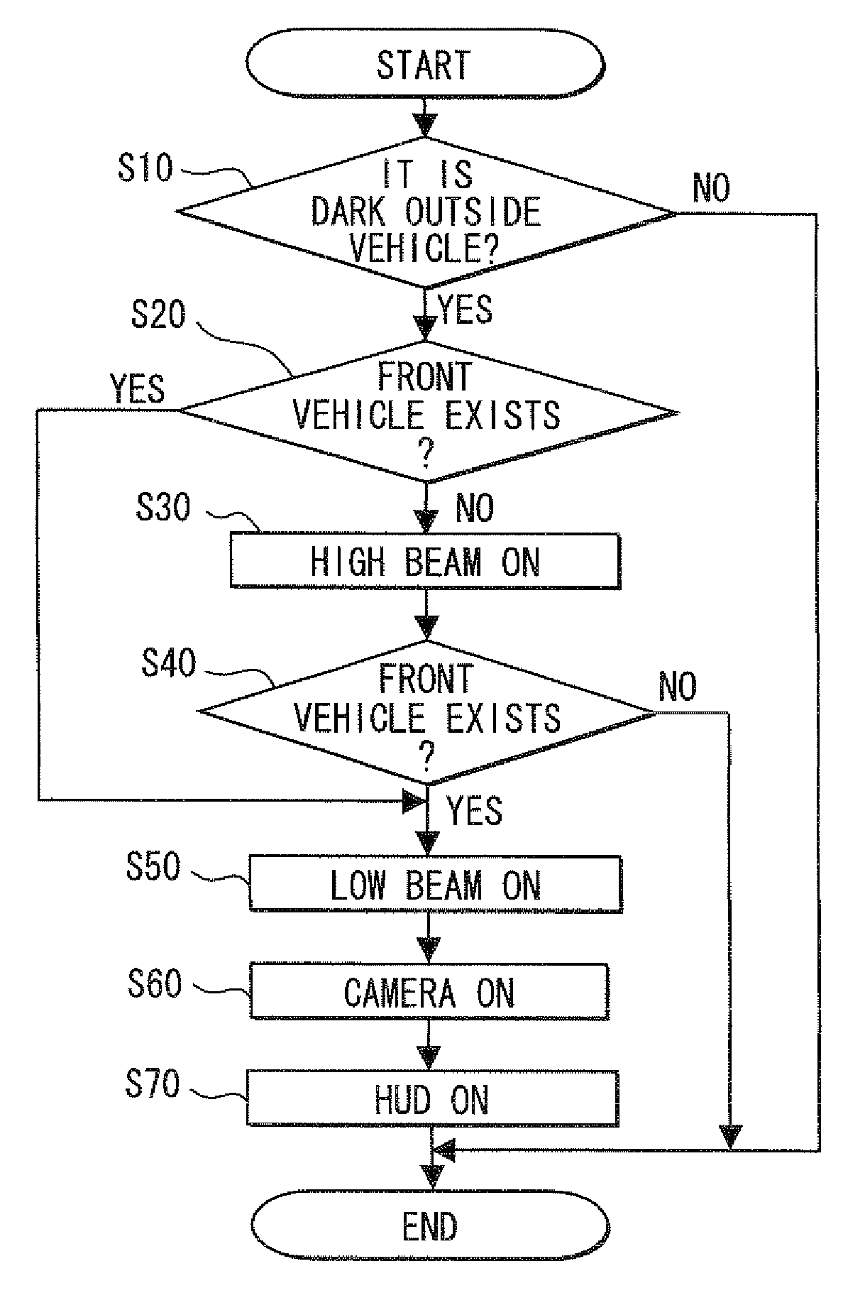
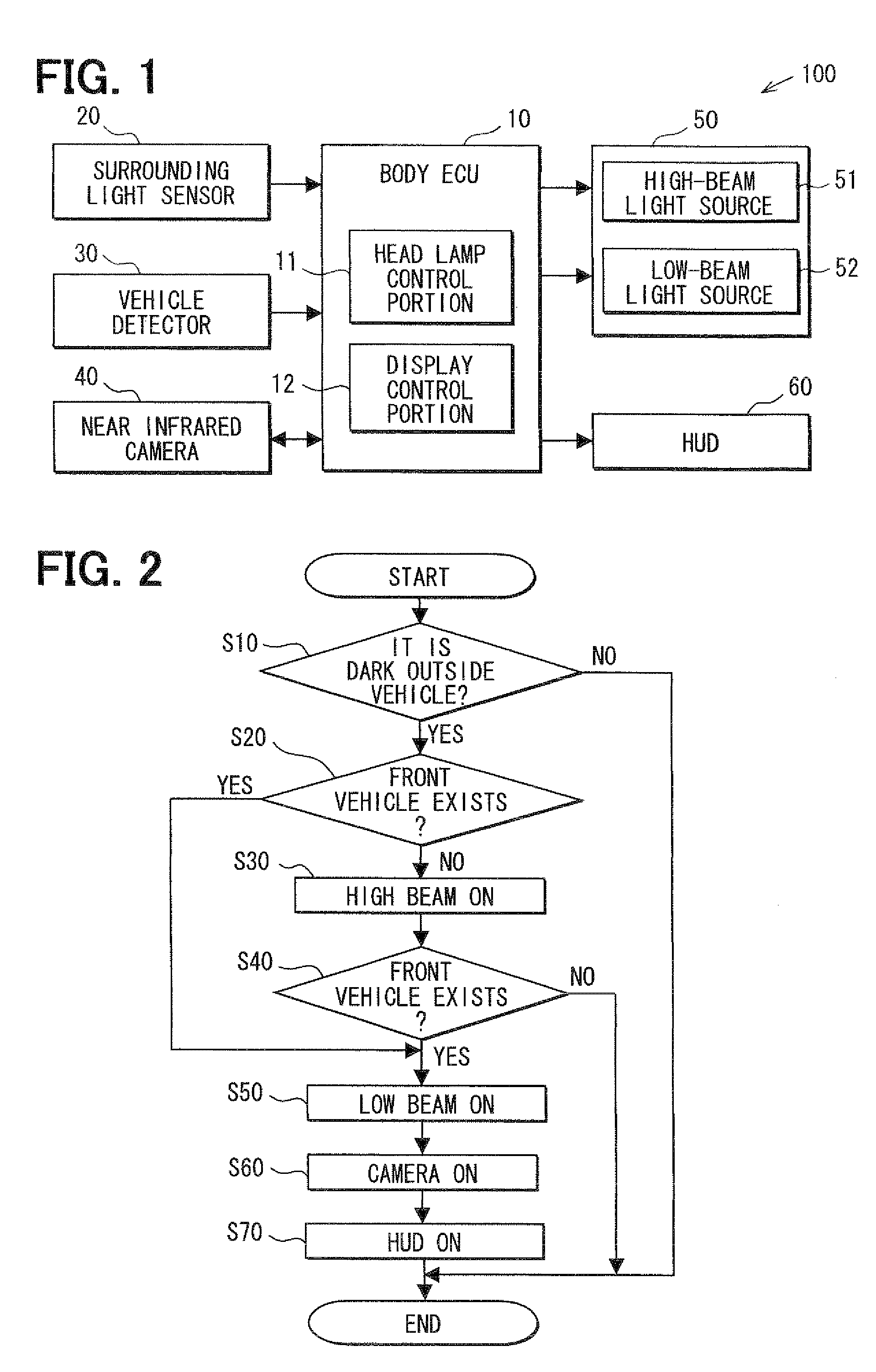
[0017]One embodiment of the present invention is described referring to accompanying drawings. FIG. 1 is a block diagram showing a schematic configuration of a vision assist apparatus according to the one embodiment of the present invention.

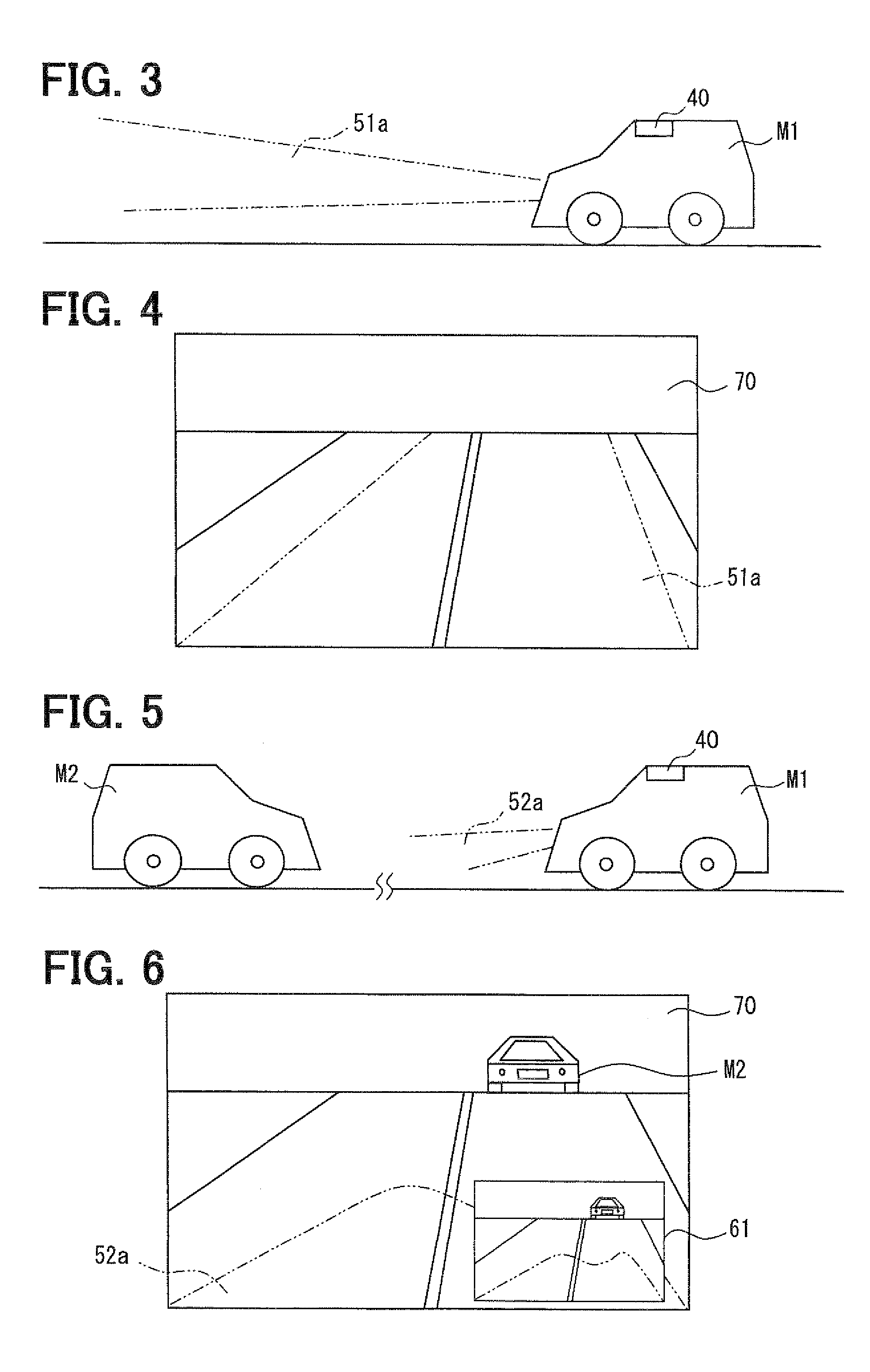
[0018]The vision assist apparatus of the present embodiment is designed to be mounted on a vehicle, and assists a vision of a driver in the vehicle, specially when an ambient environment is dark (e.g., at night). As shown in FIG. 1, the vision assist apparatus includes a body ECU (electronic control unit) 10, a surrounding light sensor 20, a vehicle detector 30, a near infrared camera 40, a headlamp 50, and an HUD (head up display) 60, all of which are electrically connected with the body ECU 10.

[0019]The body ECU 10 includes a CPU, a ROM, a RAM, an input / output circuit, a headlamp control portion 11, and a display control portion 12. The CPU serves as a central processing unit that executes well-known various computation processes. The ROM store...


PUM


Abstract

A vision assist apparatus for assisting a vision of a driver in a vehicle having a headlight includes a night vision camera, a display device, detecting unit, a lighting controlling unit, and a display controlling unit. The night vision camera is configured to capture an image around the vehicle. The display device is configured to display the image captured by the night vision camera. The detecting unit is configured to detect an object that exists in front of the vehicle. The lighting controlling unit controls that the headlight the vehicle. The lighting controlling unit operates the headlight in a high beam mode when the detecting unit does not detect the object while the headlight is on. The display controlling unit causes the display device to display the image captured by the night vision camera when the object exists in front of the vehicle.

Description

CROSS REFERENCE TO RELATED APPLICATION[0001]This application is based on and incorporates herein by reference Japanese Patent Application No. 2006-355969 filed on Dec. 28, 2006.BACKGROUND OF THE INVENTION[0002]1. Field of the Invention[0003]The present invention relates to a vision assist apparatus that assists a vision of a driver in a vehicle.[0004]2. Description of Related Art[0005]Conventionally, JP-A-2000-198385 describes an example of a conventional apparatus for assisting a vision of a driver in a vehicle.[0006]In the apparatus described in JP-A-2000-198385, an optical axis of a headlight of the vehicle is adjustable in up, down, right, and left directions, and a light quantity of the headlight is also adjustable. When it is detected that an opposed vehicle is approaching, the optical axis and the light quantity are arranged or made in a reference position and in a reference quantity, respectively. However, when the opposed vehicle is not detected to be approaching, the optic...

Claims


Application Information

Patent Timeline
Patent Type & Authority Applications(United States)
IPC IPC(8): H04N7/18
CPCB60Q1/143B60Q2300/314B60Q2300/41H04N7/18B60Q2300/45B60R1/00B60Q2300/42
Inventor KATOU, KENJITAKEHISA, SATOSHI
Owner DENSO CORP
Why Eureka
Try Eureka