
Backlight and ambient light sensor system

a technology of ambient light and sensor system, applied in the field of electronic devices, can solve the problems of limited battery life of these portable devices, complex portability of portable devices, etc., and achieve the effect of reducing the output weight of ambient light sensors

Active Publication Date: 2008-07-10
APPLE INC
View PDF95 Cites 100 Cited by
  • Summary
  • Abstract
  • Description
  • Claims
  • Application Information

AI Technical Summary

Benefits of technology

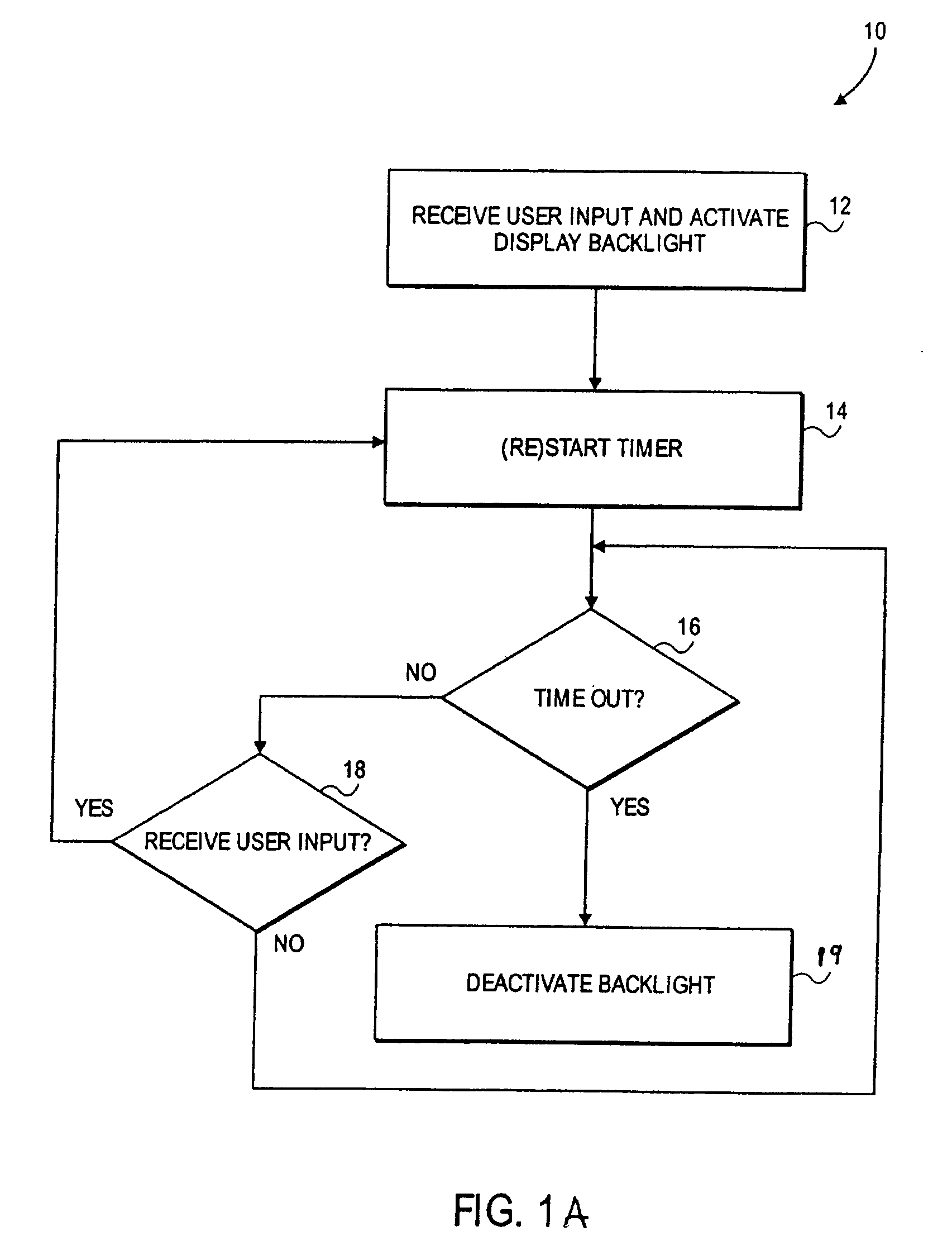
[0006]According to some embodiments of the inventions, a method of operating a display device of an electronic device, includes receiving a user setting of a display control parameter, and altering, based on the user setting, an effect of an ambient light sensor value (ALS) on control of the display control parameter. Also, the setting may be a change of the user setting and the altering may automatically be caused by the change. Moreover, the display control parameter may be the physical brightness level of a backlight of a display of a portable device. In some cases, the display control parameter may be proportional to the user setting and the light sensor value. The method may additionally include displaying a physical brightness level of a backlight of a display of an electronic device according to the display control parameter.
[0007]Further, according to some embodiments of the inventions, a method of operating a display of an electronic device may include receiving a change to a user selected brightness level of a display brightness level, and alte...

Problems solved by technology

Such portable devices have grown more complex over time, incorporating many features including, for example, MP3 player capabilities, web browsing capabilities, capabilities of personal digital assistants (PDAs) and the like.
The battery life of these portable devices, however, can be limited.
The display device may also be a significant draw of power for non-portable electronic devices.

Method used


Image

  • Backlight and ambient light sensor system
  • Backlight and ambient light sensor system
  • Backlight and ambient light sensor system

Examples


Embodiment Construction

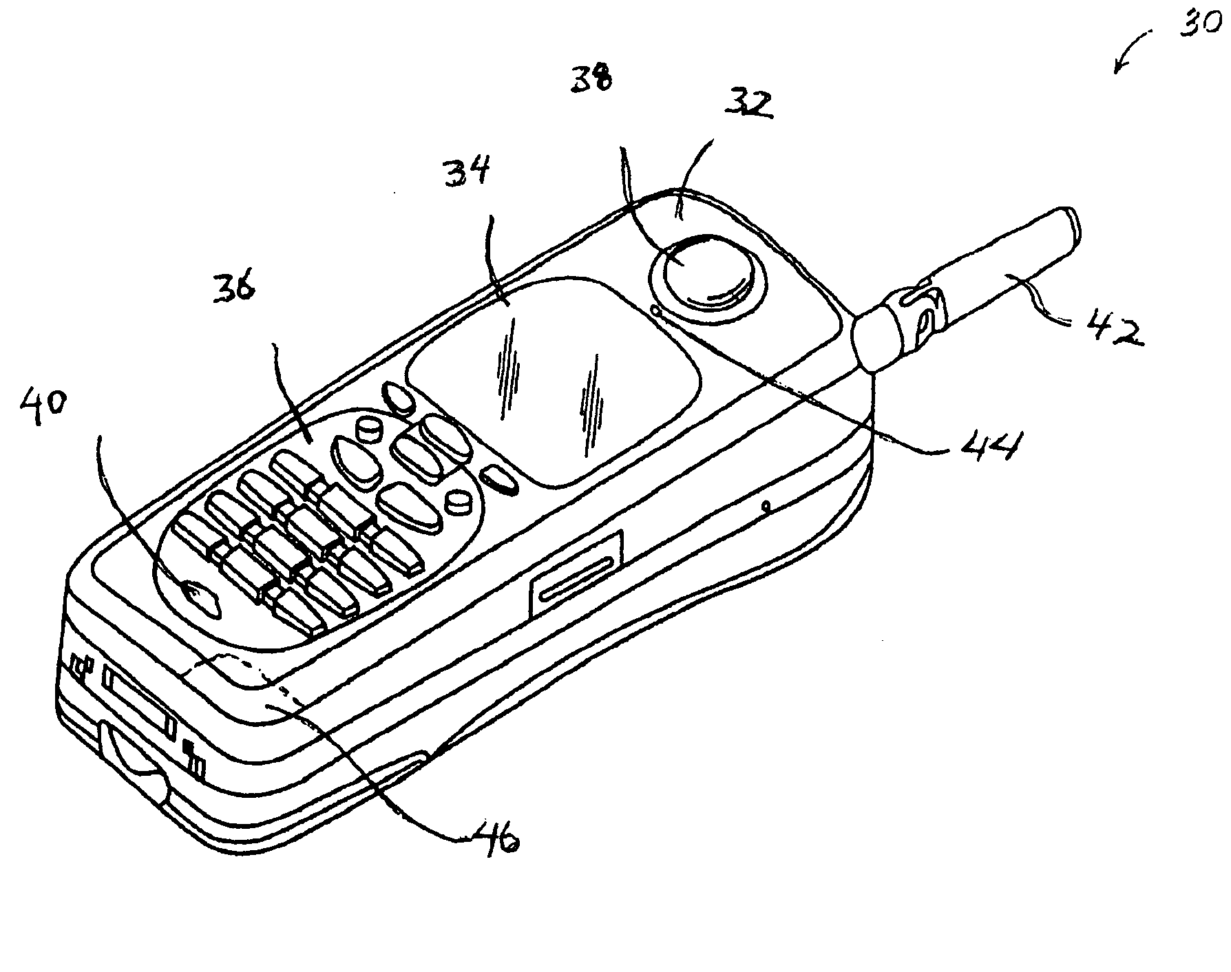
[0030]Various embodiments and aspects of the inventions will be described with reference to details discussed below, and the accompanying drawings will illustrate the various embodiments. The following description and drawings are illustrative of the invention and are not to be construed as limiting the invention. Numerous specific details are described to provide a through understanding of various embodiments of the present invention. However, in certain instances, well-known or conventional details are not described in order to provide a concise discussion of embodiments of the present inventions.

[0031]Some portions of the detailed descriptions which follow are presented in terms of algorithms which include operations on data stored within a computer memory. An algorithm is generally a self-consistent sequence of operations leading to a desired result. The operations typically require or involve physical manipulations of physical quantities. Usually, though not necessarily, these ...


PUM


Abstract

Apparatuses and methods to operate a display device of an electronic device. In some embodiments, a method includes receiving a user setting of a display control parameter, and altering, based on the user setting, an effect of an ambient light sensor value (ALS) on control of the display control parameter. Also, according to embodiments of the inventions, a method of operating a display of an electronic device includes receiving a change to one of a display brightness output level and an ambient light sensor output level, and altering, according to the change, a display contrast output level. In some embodiments, a method of operating a proximity sensor of an electronic device includes receiving a light sensor output, and altering, according to the output, an on / off setting of a proximity sensor. Other apparatuses and methods and data processing systems and machine readable media are also described.

Description

FIELD OF THE INVENTION[0001]This invention relates to the field of electronic devices and, in particular, to systems and methods for operating a display device of a portable device.BACKGROUND OF THE INVENTION[0002]Electronic portable and non-portable devices, such as computers and cell phones, are becoming increasingly common. Such portable devices have grown more complex over time, incorporating many features including, for example, MP3 player capabilities, web browsing capabilities, capabilities of personal digital assistants (PDAs) and the like.[0003]The battery life of these portable devices, however, can be limited. Often, the primary draw of battery power is the display device for these portable devices and, in particular, the backlight, which can be used to illuminate the display device. The display device may also be a significant draw of power for non-portable electronic devices. The backlight may provide a background light or color over which text, pictures and / or images a...

Claims


Application Information

Patent Timeline
IPC IPC(8): G09G3/36H05B44/00
CPCG06F1/3203G06F1/3265G09G3/3607G09G2320/0606G09G2320/0626Y02B60/1242G09G2360/144H04M1/22H04M2250/12H04W52/0254G09G2320/066Y02D10/00Y02D30/70
Inventor HERZ, SCOTT M.YEPEZ, ROBERTO G.CULBERT, MICHAEL F.FORSTALL, SCOTT
Owner APPLE INC
Learn More