Offset Compensated Position Sensor and Method

a position sensor and offset compensation technology, applied in the field of sensors, can solve the problems of increasing system cost and weight, generating low frequency noise of most position sensing transducers, and several unwanted electrical signals generally characterized as noise, so as to reduce the size and weight, reduce or eliminate the number of semiconductor devices

Inactive Publication Date: 2006-11-23
WOLFF CONTROLS
View PDF12 Cites 5 Cited by
  • Summary
  • Abstract
  • Description
  • Claims
  • Application Information

AI Technical Summary

Benefits of technology

[0012] In a second embodiment of the invention, a significant size reduction and an increase in reliability can be achieved by reducing or eliminating the number of semiconductor devices on the chip. In a first embodiment, the semiconductor devices required to implement the clock with both a short and a long alternation, the counter, and the DAC take up significant amounts of space on the die. The clock circuit longer alternation requires a separate counter to implement an increase the time of the alternation. Significant decreases in size could be realized by reducing the number of bits of the counter and DAC H.
[0013] However, a fast-running clock without the longer alternation would rapidly drive the dynamic signal down to the zero reference level or below. Since in the original version, the only purpose of reducing the offset output level is to reduce the power consumed by the sensor and related power supplies, an increase in the step size simply means that more power is consumed. However, any such step increase in a free-running version of the offset elimination circuit means that any changes in level during the dynamic signal level would become objectionable. Decreasing the number of devices in other parts of the circuit that process the dynamic signal would also contribute to a decrease in output quality. It is likely therefore that the only way to decrease die size and increase reliability are to eliminate the longer alternation and to decrease the number of bits of the counter and the DAC and to prevent the offset elimination circuit from operating during the dynamic signal event.
[0014] This could be accomplished easily in most cases by using an external clock only to generate signals that allow compensation only during the time that the dynamic signal is known to be absent. An example application is in the monitoring of diesel fuel injection systems, where the target is known to be at rest a large part of the time, and the actual movement of the target is initiated by a control system so the approximate timing of the dynamic event is known.
[0015] In some of the aforementioned sensors, a quantity of useful information can be obtained about the sensor and its environment if the amount of static offset can be obtained. For instance, the amount of time it takes the sensor offset compensation circuitry to eliminate the offset can be used to determine the status of magnets used to generate magnetic fields if the time taken is proportional to the field detected. Likewise, if these sensors contain an internal clock and offset compensation circuit, the timing and power drawn by the internal clock can be used to determine the temperature of the sensor. Reference is made to pending application, U.S. Ser. No. 10 / 345,847 for “Multiplexed Autonomous Sensors and Monitoring System and Associated Methods”, the disclosure of which is incorporated herein by reference in its entirety. In these cases, an additional advantage is gained by leaving an internal clock on the sensor and causing this internal clock to provide offset compensation at specific times during which the temperature of the sensor is desired or during which the static magnetic field is desired. The length of time taken to eliminate the offset yields the value of the offset, and the power drawn by the digital pulses yield the sensor temperature. However, to prevent the internal clock from running all the time and possibly reducing the sensor output during a dynamic event, the internal clocked offset compensation system must only respond to events or circumstances that cause the offset to decrease. Provided this requirement is met, there is an advantage to having an internal clock and an internally controlled offset compensation circuit on these sensors, even though an external clock could be used alone to accomplish the same operations.

Problems solved by technology

The wiring of these sensors to a remotely located engine monitoring and control system must be designed to accommodate extreme temperatures and vibrations and adds cost and weight to the system.
An ideal output signal contains only this information; however, several unwanted electrical signals generally characterized as noise are also usually generated or otherwise transmitted along with the desired position signal.
Most position sensing transducers also generate low frequency noise in the form of a slowly drifting or static DC offset, or error signals that may be a significant portion of the total overall signal.
This slowly changing or static error signal causes numerous problems in employing two-wire current output position sensors.
This adds to the temperature of the devices in the sensor, reducing the maximum ambient temperature that the sensor can operate at and reducing overall sensor reliability.
This power is wasted and also requires a higher power capability for resistors, by way of example.
A further limitation on these type sensors is that especially upon power-up, the sensor should desirably not draw a large amount of current and should automatically calibrate itself so that no excessive current is drawn at any time during its operation.
For instance, on vehicles utilizing storage batteries, the initial power-up of these sensors usually occurs at the same time that the battery is being used to crank the engine, reducing the amount of power available to power the sensors.

Method used


Image

  • Offset Compensated Position Sensor and Method
  • Offset Compensated Position Sensor and Method
  • Offset Compensated Position Sensor and Method

Examples


Embodiment Construction

[0020] The present invention will now be described more fully hereinafter with reference to the accompanying drawings, in which preferred embodiments of the invention are shown. This invention may, however, be embodied in many different forms and should not be construed as limited to the embodiments set forth herein. Rather, these embodiments are provided so that this disclosure will be thorough and complete, and will fully convey the scope of the invention to those skilled in the art. Like numbers refer to like elements throughout, and prime notation is used to indicate similar elements in alternate embodiments.

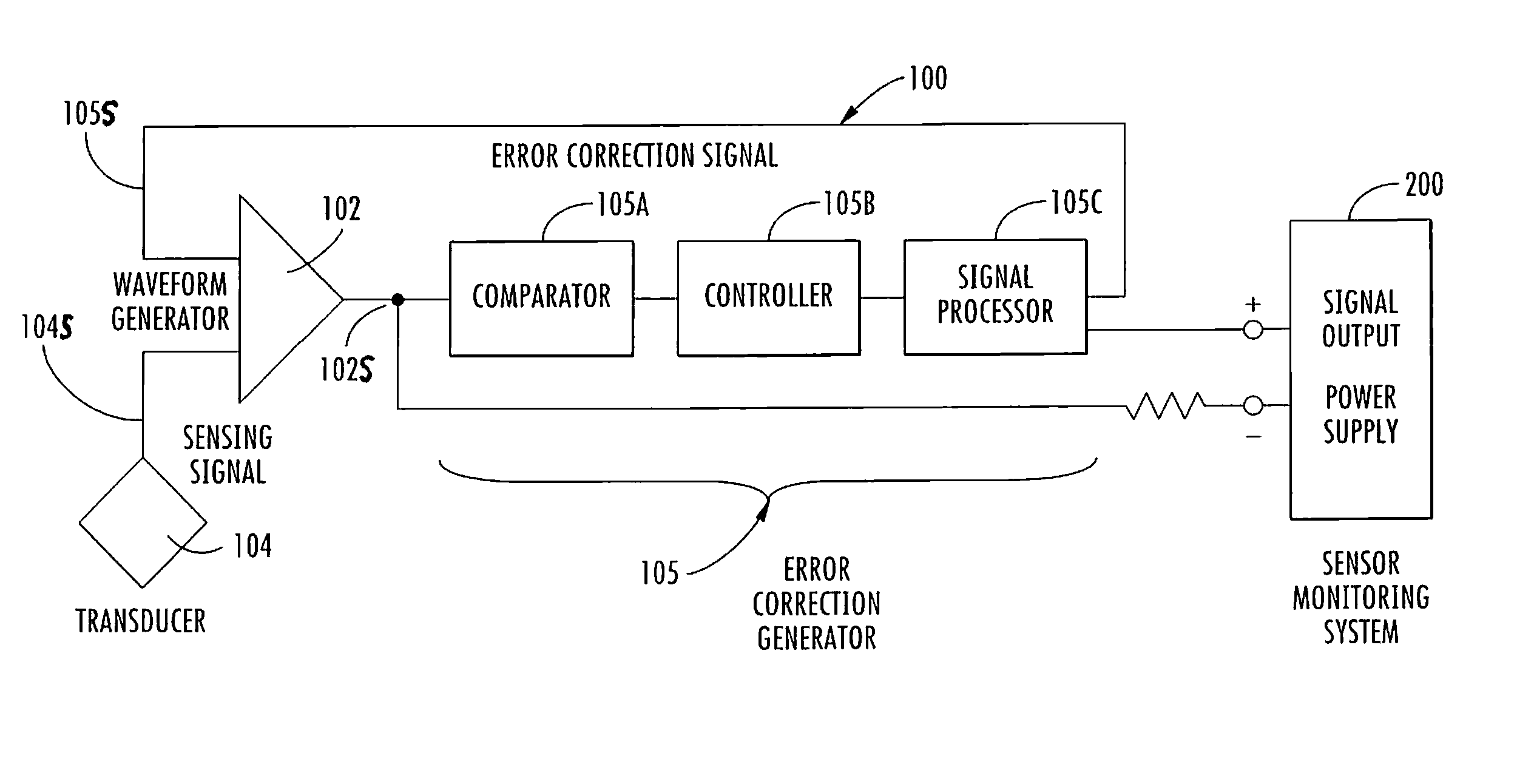
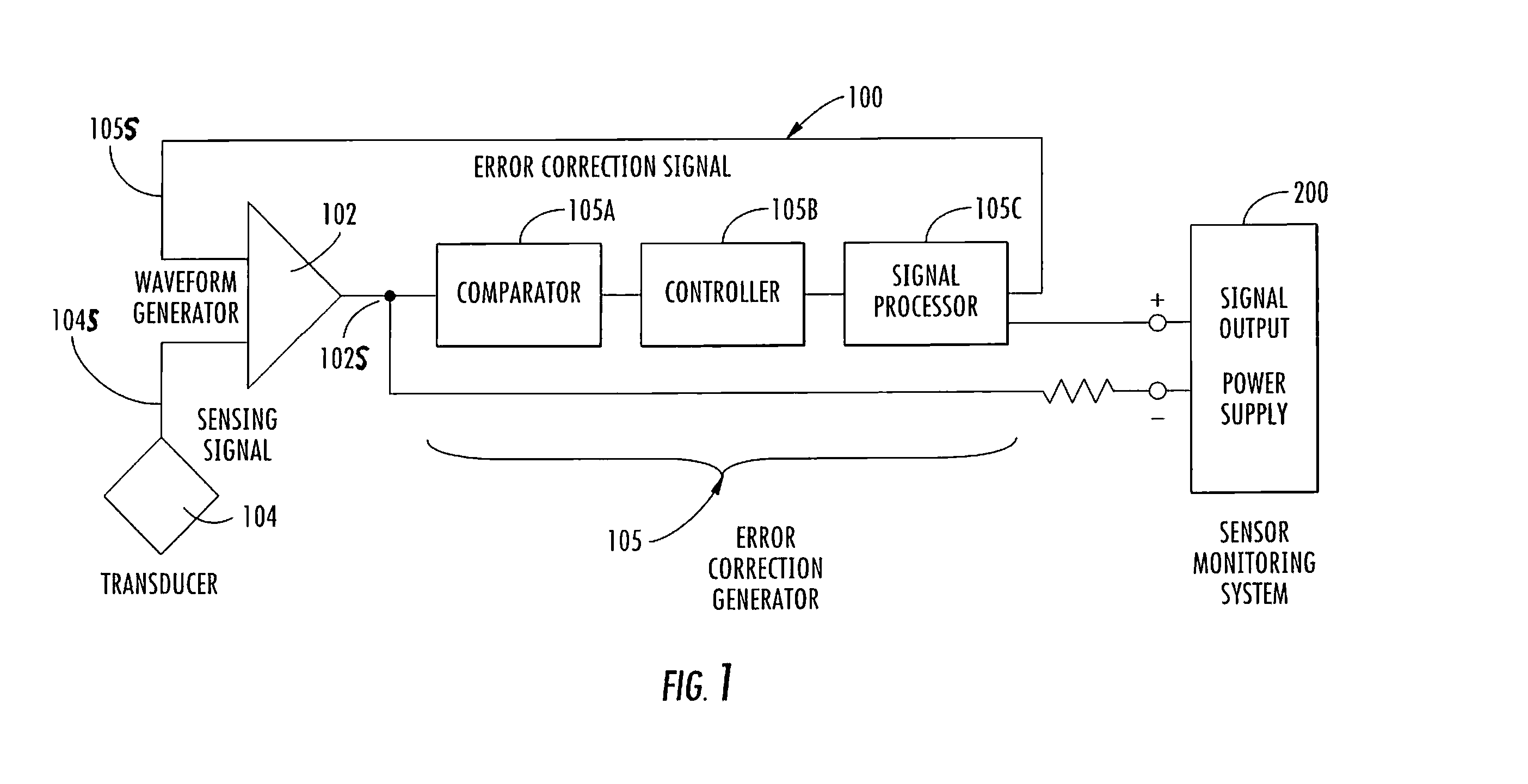
[0021] With reference initially to FIG. 1, a position sensor 100 is herein described as including a waveform generator 102 operable for receiving an unconditioned sensing signal 104S from a transducer 104 and modifying the unconditioned sensing signal responsive to an error correction signal 105S for providing a conditioned sensing signal 102S. As will herein de described, ...


PUM


Abstract

A position sensor monitors relatively fast moving objects with signal conditioning for reduced power and reduced wiring. A transducer and related circuitry generate a dynamic signal proportional to a position of a moving object and also generate one or more low frequency or static (DC or zero frequency) error signals. The low or zero frequency error signals are removed and a position signal is generated using only two connections to a remote sensor monitor, thus allowing ease in multiplexing and reduced wiring. Circuit options allow placing less circuitry on the sensor itself for small size or more circuitry on the sensor for less control requirement.

Description

CROSS-REFERENCE TO RELATED APPLICATIONS [0001] This is a continuation-in-part application claiming the benefit of U.S. Provisional Application Ser. No. 60 / 710,750 for “Position Sensor Including Error Level Compensation” having filing date Aug. 24, 2005, and of U.S. application Ser. No. 10 / 995,963 for “Offset Compensated Position Sensor and Method” having filing date of Nov. 23, 2004, which itself claims the benefit of U.S. Provisional Application Ser. No. 60 / 524,799 for “Offset Compensated Position Sensor,” and U.S. Provisional Application Ser. No. 60 / 524,919 for “Minimized Cross-Section Sensor Package,” both having filing date Nov. 25, 2003, all disclosures of which are herein incorporated by reference in their entirety, and all commonly owned with the instant application.FIELD OF THE INVENTION [0002] The present invention generally relates to sensors, and in particular to position and motion sensors. BACKGROUND OF THE INVENTION [0003] Many mechanical systems contain moving parts n...

Claims


Application Information

Patent Timeline
Patent Type & Authority Applications(United States)
IPC IPC(8): G01R13/00
CPCG01D3/036
Inventor SMITH, MARSHALL E.STETTLER, RICHARD W.
Owner WOLFF CONTROLS
Why Eureka
Try Eureka