Magnetic detection element and detection method

a detection element and magnetic technology, applied in the field of magnetic detection elements, can solve problems such as the inability to detect magnetic particles, and achieve the effect of improving detection sensitivity and lowering the sensor outpu

Inactive Publication Date: 2010-08-26
CANON KK
View PDF11 Cites 1 Cited by
  • Summary
  • Abstract
  • Description
  • Claims
  • Application Information

AI Technical Summary

Benefits of technology

[0013]In detection of a local magnetic field Hs generated by a magnetic particle by a parallel FG sensor element, a change of the relative position of the magnetic particle to the detecting coil can lower the sensor output as the result of counteraction in the induced electromotive force in the sensor element. Therefore, under some conditions, even in the presence of magnetic particles, the magnetic particles can not be detected owing to insufficient output of the sensor.
[0014]The present invention has been accomplished to solve the aforementioned problems of conventional techniques. The present invention intends to provide a magnetic detection element having improved sensitivity in detection of a magnetic field formed by a detection object substance, and a detection method therewith.

Problems solved by technology

Therefore, under some conditions, even in the presence of magnetic particles, the magnetic particles can not be detected owing to insufficient output of the sensor.

Method used


Image

  • Magnetic detection element and detection method
  • Magnetic detection element and detection method
  • Magnetic detection element and detection method

Examples


example 1

[0081]This Example describes an immunological sensor employing a magnetic detection element and a detection method of the present invention.

(i) Sensor Mechanism

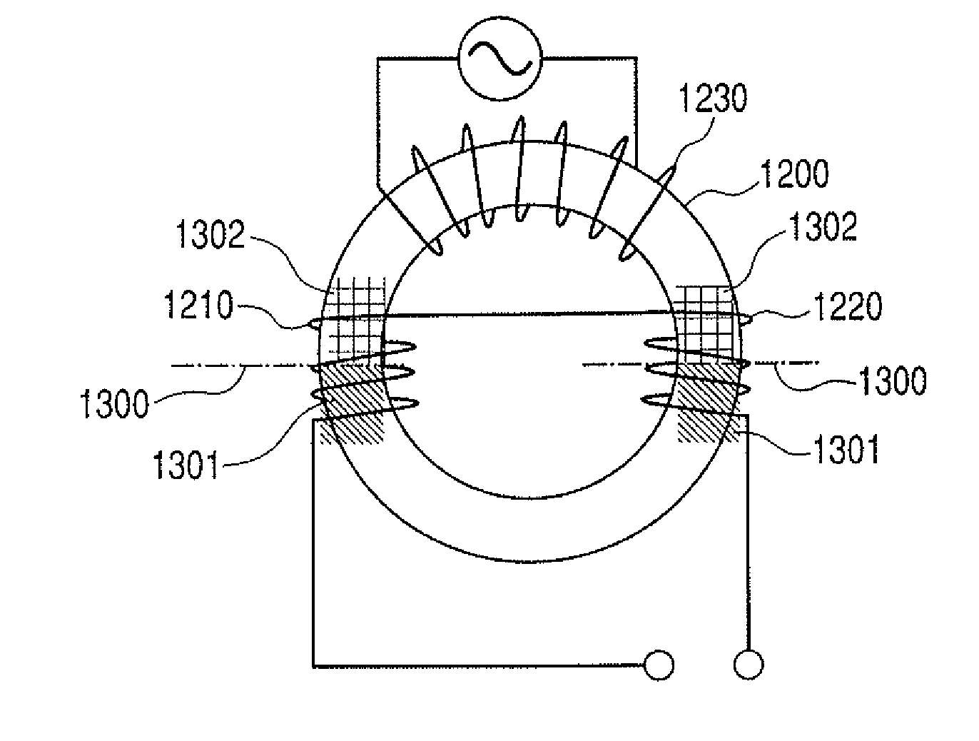
[0082]The constitution of the FG sensor element of this Example is described below. FIG. 10 illustrates schematically an external view of the parallel type FG sensor element of this Example. As illustrated in FIG. 10, soft magnetic core 1200 has exciting coil 1230, detecting coils 1210, 1220 for detecting magnetic change in thin-filmed soft magnetic core 1200.

[0083]The process for producing the FG sensor element of this Example is described briefly below. In this Example, the FG sensor element is produced through a semiconductor production process. A nonmagnetic material such as SiO2 is placed on soft magnetic core 1200, and detecting coils 1210, 1220, and exciting coil 1230 are wound around the soft magnetic core. The material for the soft magnetic core is exemplified by FeCo alloys.

[0084]Before winding the coils, a first re...

example 2

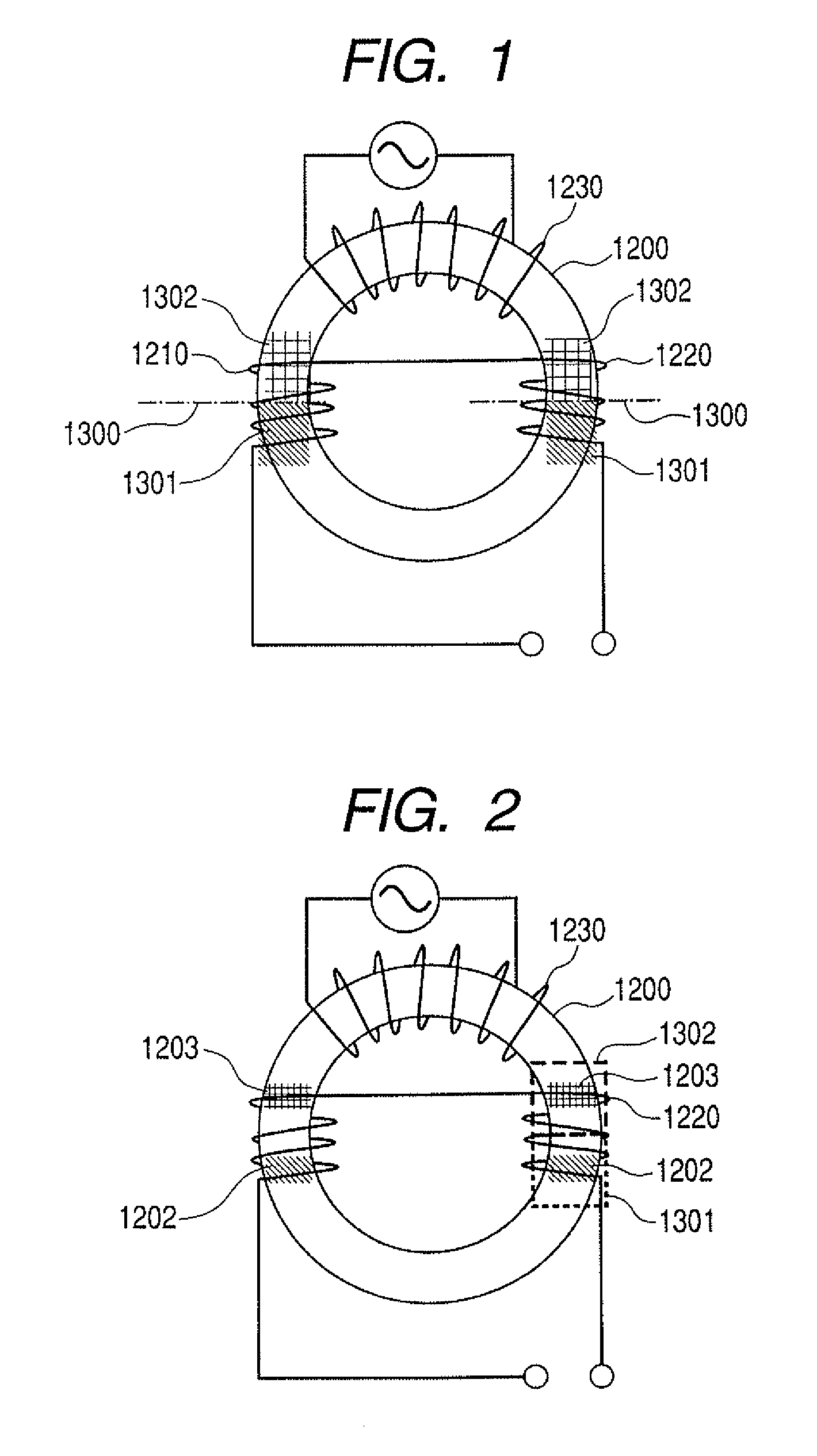
[0091]This Example describes application of the constitution illustrated in FIG. 8 to the element in Example 1. FIG. 12 illustrates schematically the external view of the parallel type FG sensor of this Example.

[0092]As illustrated in FIG. 12, the FG sensor of this Example comprises, detecting coils 1211, 1212 and detecting coils 1221, 1222 which are reversely wound and provided in series in the FG sensor of Example 1. On the surface of the soft magnetic core 1200 of the portions of detecting coil 1211, 1212 connected in series, region 1303 and region 1304 like the ones illustrated in FIG. 8 are provided. The same regions are provided also on the surface of soft magnetic core 1200 of detecting coils 1221, 1222.

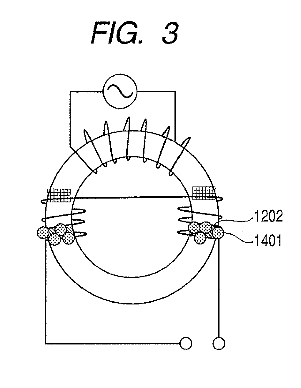
[0093]Magnetic particle-immobilizing film 1202 is formed at least a part of the region corresponding to region 1303, and magnetic particle-non-immobilizing film 1203 is formed at least a part of the region corresponding to region 1304. In the measurement, the magnetic field is...


PUM


Abstract

A magnetic detection element, comprises a core composed of a soft magnetic material, a detecting coil for detecting a magnetic field applied to the core, and an exciting coil for applying an alternating magnetic field to the core, wherein the surface of the core is divided into a first region and a second region in the longitudinal direction of the detecting coil, the first region and the second region being different in affinity for a detection object substance.

Description

TECHNICAL FIELD[0001]The present invention relates to a magnetic detection element for detecting a magnetic particle or a non-magnetic substance labeled with a magnetic particle, and relates also to a method for magnetic detection.BACKGROUND ART[0002]Radio immunoassay (RIA) or immunoradiometric assay (IRMA) are known as quantitative immunoassay since a long time ago. In these assay methods, an affinitive antigen (or antibody) is labeled with a radioactive nuclide, and a target substance (antibody or antigen) is assayed indirectly by measurement of the specific radioactivity. This assay method is useful for clinical diagnosis owing to the high sensitivity. However, this method requires security against the radioactive nucleotide, and requires a facility or apparatus for handling the radioactive nucleotide. Therefore, simpler and safer methods other than the radiometric method are proposed which utilize a label such as a fluorescent substance, an enzyme, an electrochemical luminescent...

Claims


Application Information

Patent Timeline
Patent Type & Authority Applications(United States)
IPC IPC(8): G01R33/04
CPCG01R33/063G01R33/18G01R33/1269G01R33/04
Inventor UEDA, MIKIIKEDA, TAKASHI
Owner CANON KK
Why Eureka
Try Eureka