Multifunction timer device

a multi-functional, timer technology, applied in the direction of electromechanical unknown time interval measurement, instruments, etc., can solve the problems of difficult to stay ahead of them and prioritize those chores, and achieve the effect of simple and easy programming

Inactive Publication Date: 2008-07-10
MORSE KEVIN C
View PDF28 Cites 5 Cited by
  • Summary
  • Abstract
  • Description
  • Claims
  • Application Information

AI Technical Summary

Benefits of technology

[0011]An object of the present invention is to provide a multifunction timer device for associating particular tasks with particular times, which can be programmed simply and easily for use in a variety of applications.
[0012]Further objects of the present invention are to provide an inexpensive and reliable device for associating a time with an object; to provide a device that can be affixed to many different surfaces using an adhesive or other suitable means; and to provide a timer device that is compact in size while maintaining an easy to use interface.

Problems solved by technology

With many of these time demands operating simultaneously (as they almost always do), it can be difficult to stay ahead of them and to prioritize those chores that need to be accomplished most urgently.

Method used


Image

  • Multifunction timer device
  • Multifunction timer device
  • Multifunction timer device

Examples


first embodiment

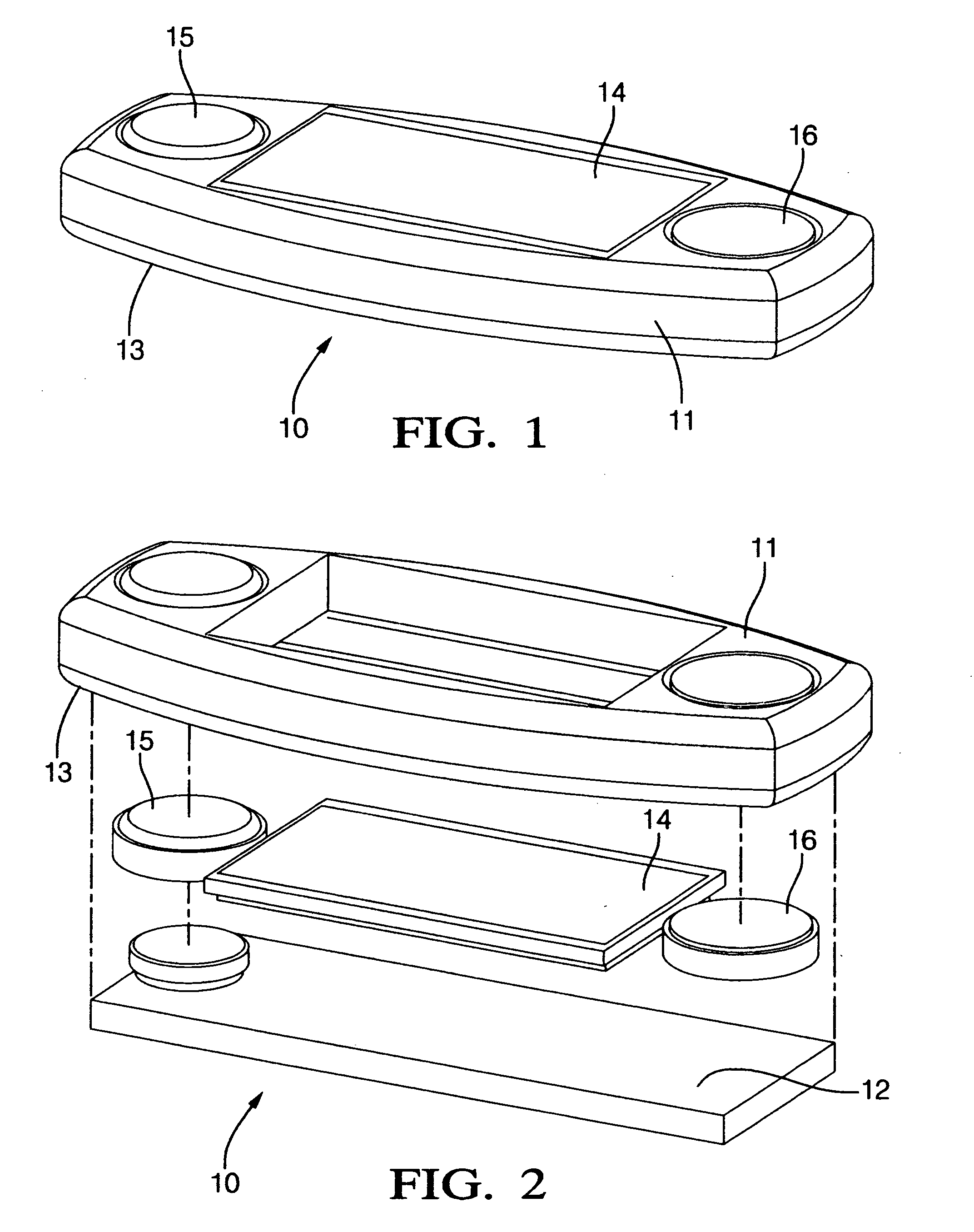
[0028]The multifunction timer device 10 according to the present invention is shown in FIGS. 1 and 2 in assembled and disassembled conditions, respectively. The timer device 10 includes a housing 11 and various electronic components contained on a printed circuit board 12 contained within the housing 11. The housing 11 includes an adhesive strip 13 or other suitable fastening structure on a surface of its back side to secure the timer device 10 to an object, such as a food package, a pill container, a medical apparatus, or virtually any other object on which the user desires to associate a particular time with a particular task by fixing an electronic time / date stamp on the object.

[0029]The timer device 10 has a display interface 14 to display time information. The preferred display interface 14 is an LCD screen that allows precise time information to be conveyed to the user and is very compact and energy efficient. The timer information can be made to display only intermittently, a...

second embodiment

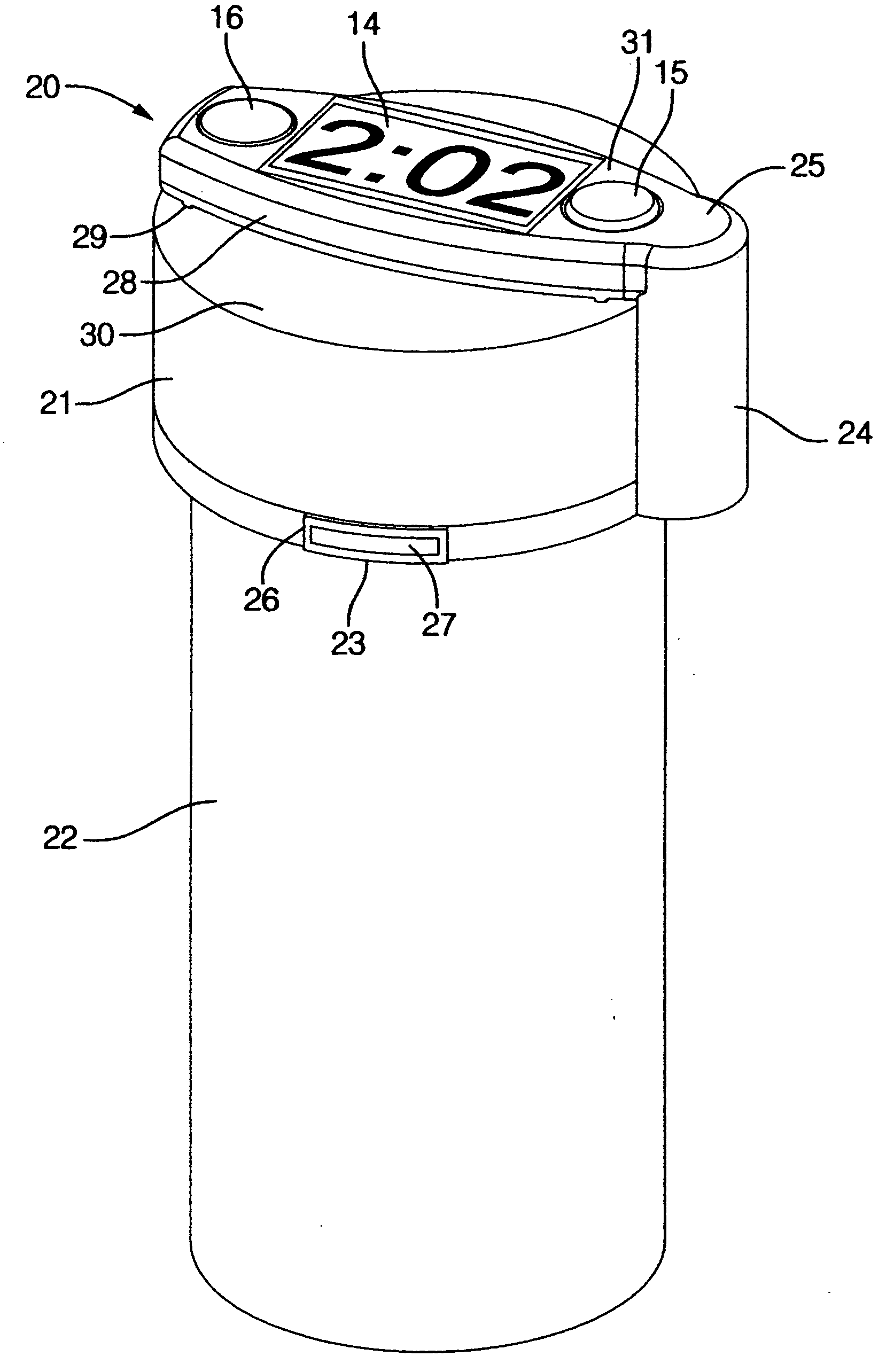
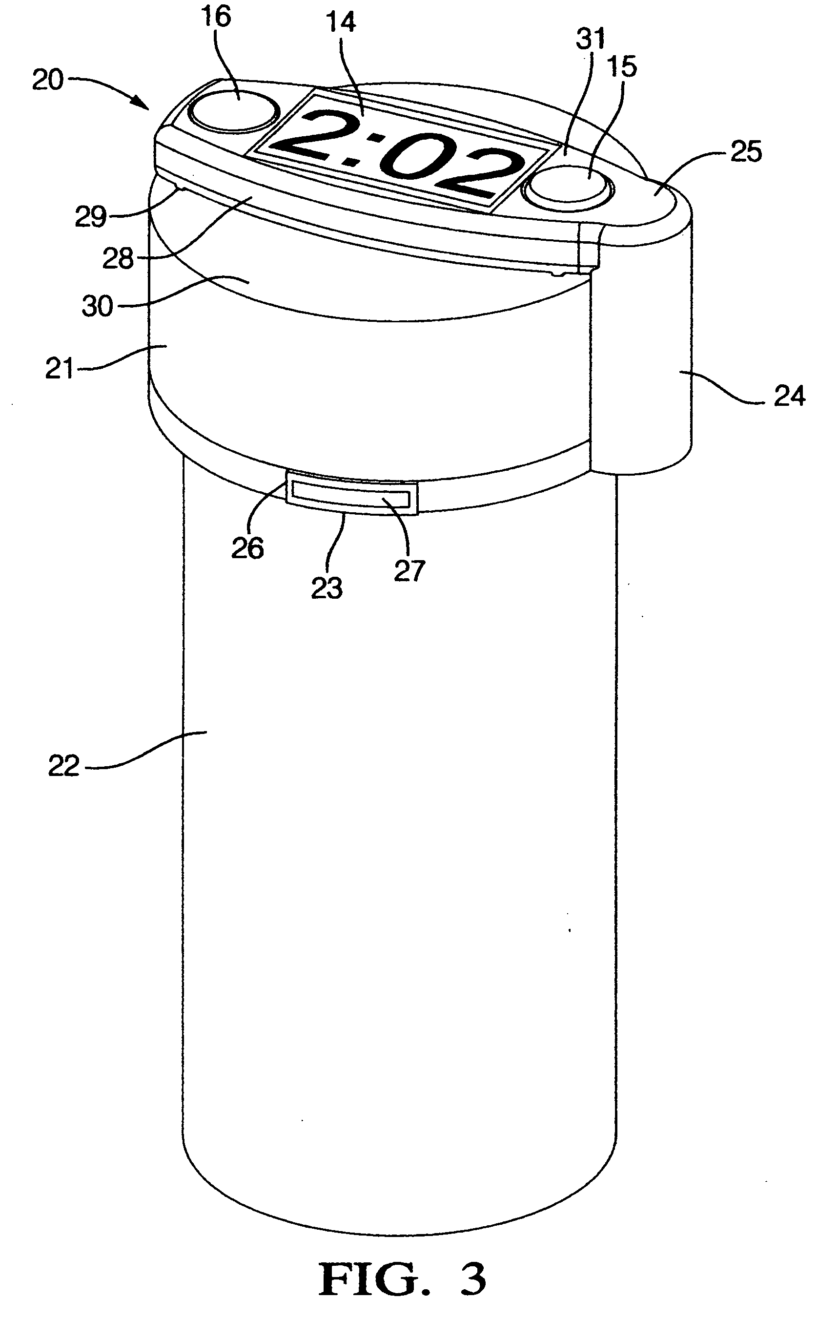
[0031]A timer device 20 according to the invention will now be explained with reference to FIGS. 3 and 4 of the accompanying drawings. The timer device 20 is particularly suitable for attaching to the lid 21 of a pill container 22 or the like to provide an electronic time / date stamp for the pill container 22.

[0032]The timer device 20 shown in FIGS. 3 and 4 includes many of the same basic features as the timer device 10 shown in FIGS. 1 and 2 and described above, and a further description of these same features will be omitted herein. The timer device 20 of the second embodiment differs from the timer device 10 of the first embodiment mainly in that it includes an automatic reset trigger 23 and an extended portion 24 of the housing 25 arranged to oppose the reset trigger 23.

[0033]The reset trigger 23 has an adhesive strip 26 or other suitable fastening means on its backside for attaching the trigger 23 to a sidewall of the container 22. The reset trigger has a conductive member 27 on...


PUM


Abstract

A multifunction timer device for providing a time / date stamp on objects includes a housing, a controller with a timer circuit contained in the housing, a display for displaying information from the timer circuit, and a multifunction input button. The input button is operable in predetermined sequences to select operating and display modes of the timer device. The input button can be operated to display an actual date or time, to display a current timer value, to select between count-up and count-down modes, and to increment a counter. An adhesive backing is provided for attaching the timer device to an object. A communications link is provided for interfacing the controller with an external programmer. A reset trigger is used to automatically reset the timer device when the object is moved in a particular way, such as when a lid is removed from a pill container.

Description

RELATED APPLICATIONS[0001]This application is a Divisional of a pending application entitled “Multifunction Timer Device”, U.S. Ser. No. 10 / 844,150, filed 12 May 2004, and owned by the common inventor / applicant.BACKGROUND OF THE INVENTION[0002]1. Field of the Invention[0003]The present invention relates generally to timer devices. In particular, the present invention relates to timer devices that can be attached to various objects and used to associate a particular time with the object.[0004]2. Description of the Related Art[0005]Many tasks in the home or in industry are time dependent. Food and pharmaceuticals are perishable. Equipment needs regular maintenance. With many of these time demands operating simultaneously (as they almost always do), it can be difficult to stay ahead of them and to prioritize those chores that need to be accomplished most urgently.[0006]Some people use small, hand-written labels to mark the date that leftovers went into the freezer. Cars often carry sma...

Claims


Application Information

Patent Timeline
Patent Type & Authority Applications(United States)
IPC IPC(8): G04B47/00G04F8/00
CPCA61J7/0472G04G9/126G04F10/00G04F1/005
Inventor MORSE, KEVIN C.
Owner MORSE KEVIN C
Why Eureka
Try Eureka