
Devices and systems for contextual and physiological-based reporting, entertainment, control of other devices, health assessment and therapy

a technology of which is applied in the field of devices and systems for contextual and physiological information, entertainment, and control of other devices, and can solve the problems of not revealing a device capable of deriving physiological and contextual parameters, consuming large amounts of power, and expensive addition of sensors

Inactive Publication Date: 2008-07-10
J FITNESS LLC
View PDF1 Cites 355 Cited by
  • Summary
  • Abstract
  • Description
  • Claims
  • Application Information

AI Technical Summary

Benefits of technology

"The present invention provides an apparatus and method for using electric field sensing to determine physiological or contextual parameters of an individual. The apparatus can be either worn by the user or in continuous proximity to the user, and can be used in areas of frequent or infrequent user-interaction. The invention also provides a low-cost and means to disambiguate sensed signals in prior art devices. Additionally, the invention provides a stationary device or network of stationary devices capable of determining or deriving the context or physiological parameters of an individual. Finally, the invention provides a more accurate health assessment system."

Problems solved by technology

But some additional sensors are costly and consume large amounts of power.
Gershenfeld et al. did not disclose a device capable of deriving a physiological and contextual parameters or a user's activity, such as walking, cycling, or energy expenditure, from a field or capacitance sensor.
Nor did Gershenfeld et al. disclose a device capable of determining or deriving a user's physiological and contextual parameters or activity with a wearable device, or in a device that is continuously proximate to a user's body.
This is a practical means for measuring total body charge, but it is impractical for continuous body monitoring.
Many of the prior art sensor devices are sophisticated, costly devices.
Such costly sensors limit the attractiveness of providing a disposable product capable of determining or deriving the context or physiological parameters of an individual.

Method used


Image

  • Devices and systems for contextual and physiological-based reporting, entertainment, control of other devices, health assessment and therapy
  • Devices and systems for contextual and physiological-based reporting, entertainment, control of other devices, health assessment and therapy
  • Devices and systems for contextual and physiological-based reporting, entertainment, control of other devices, health assessment and therapy

Examples


first embodiment

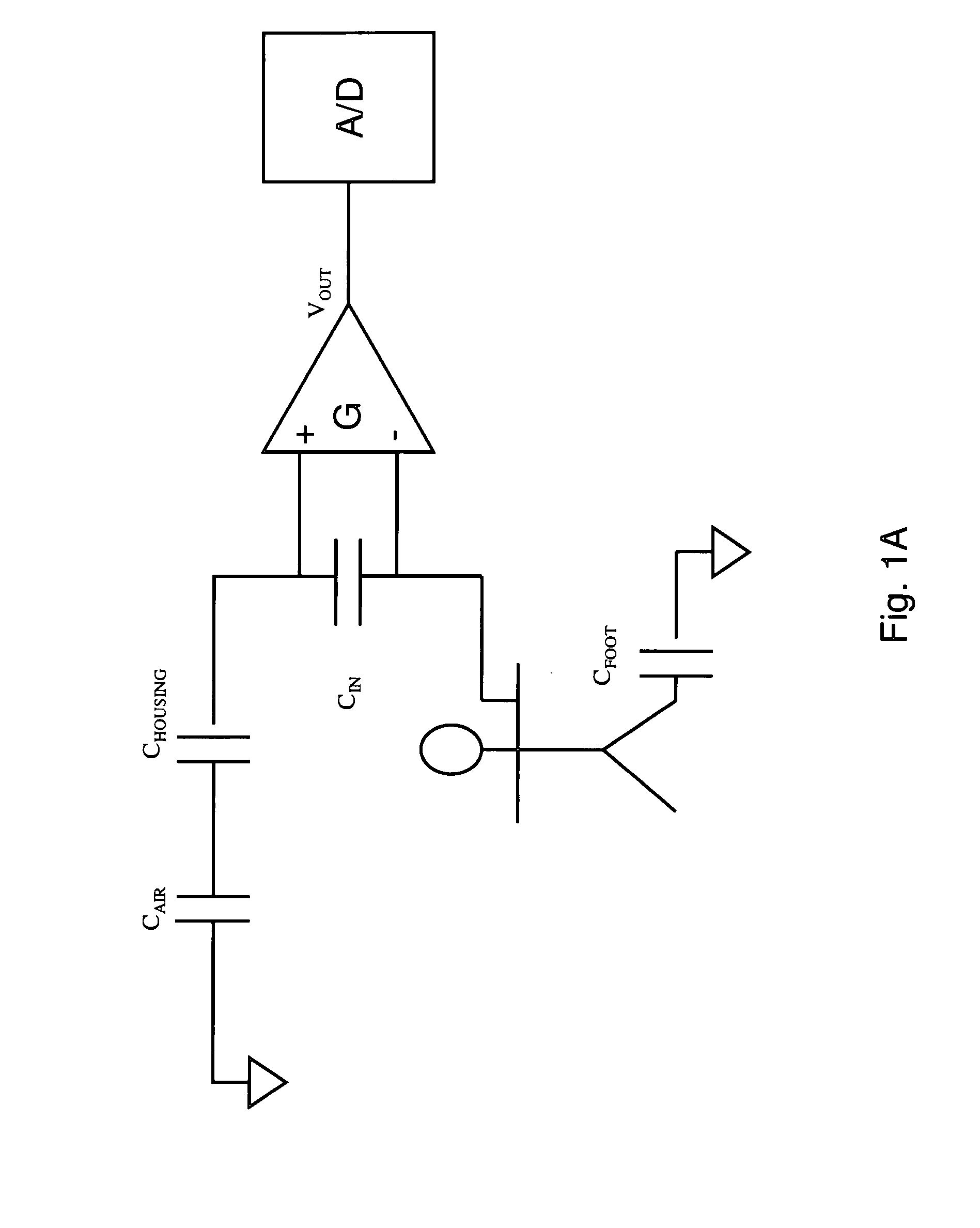
[0114]Indeed, through testing, Applicants have shown various parameters each have a signal signature, wherein the signal is generated from an electric-field sensor. Thus, the invention comprises devices and methods for utilizing electric-field data to determine physiological parameters, contextual parameters, activities, event, or body states of a user. FIG. 1B schematically depicts such a device. Many of the aspects of this schematic representation overlap with the schematic representation of the device as shown in FIG. 1. The general scheme employed in FIG. 1 is applicable to the description immediately below. Nevertheless, the particular schematic will be discussed to further clarify an embodiment of one such apparatus. The apparatus comprises a sensing device 10 having an electric-field sensor 12A of the type described above. The electric-field sensor 12A could be a sensor in any of the sensor devices or modules disclosed herein but need not necessarily configured as such. The e...

second embodiment

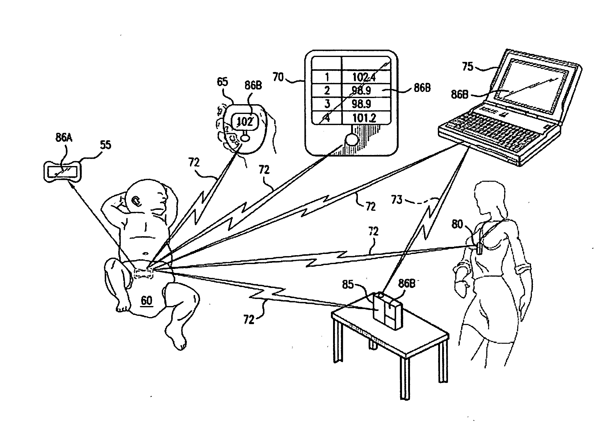
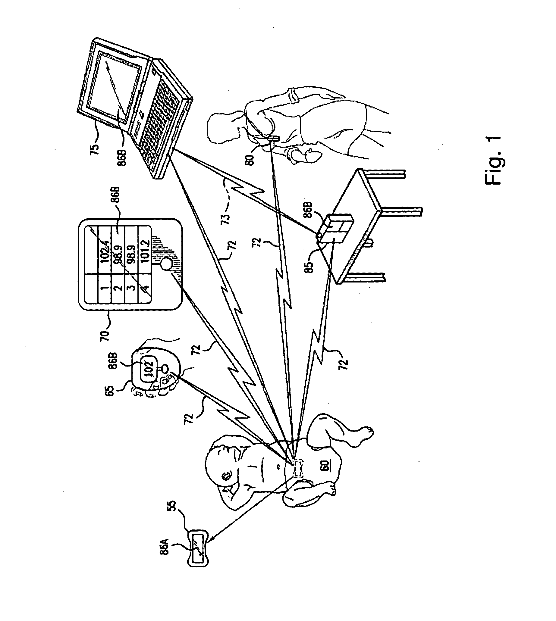
[0168]FIG. 5C illustrates module 55 which is an elongated module 130. As previously described with respect to FIGS. 5A and 5B, the housing components of module 130 are preferably constructed from a flexible urethane or an elastomeric material such as rubber or a rubber-silicone blend by a molding process, although the housing components may also be constructed from a rigid plastic material. Ambient temperature sensor 120 is located along a central portion of upper housing 95 of elongated module 130 and can be protected by sensor cover 115 if necessary, as described with respect to FIG. 5A. Elongated module 130 further has a first wing portion 131 and a second wing portion 132. Wing portions 131, 132 are located opposite to each other on either side of sensor cover 115 and can be of equal or varying lengths and widths depending on location of body being attached to requirements for adhesion and force against the body. Elongated module 130 may be adapted to conform to the size of an i...

seventh embodiment

[0198]FIGS. 11A through 11G illustrate the present invention in the form of a folded clip module 495. FIG. 11A illustrates a folded clip module 495 having a first portion 510 and a second portion 515. FIGS. 11B and 11C illustrate one embodiment of folded clip module 495. In FIG. 11B, folded clip module 495 has a first portion 510 which is constructed from a durable material, preferably of flexible urethane or an elastomeric material such as rubber or a rubber-silicone blend by a molding process. Alternatively, first portion may be a rigid plastic. First portion 510 further has a circular face 520 on which display 86A is located. As with all displays disclosed herein, display 86A visually presents continuous detected physiological or contextual measurements and other relevant, statistical data including processed data such as current parametric data, data trends, and other derived 1 data.

[0199]First portion 510 of folded clip module 495 has a narrow extension piece 521 that connects ...


PUM


Abstract

A monitoring system comprises a module having at least one sensor to determine human status information. The device may be durable or disposable. A receiver may be provided to obtain and display data from the device. The device may also display the output data. The output data comprises both detected and derived data relating to physiological and contextual parameters of the wearer and may be transmitted directly to a local recipient or remotely over a communications network. The system is capable of deriving and predicting the occurrence of a number of physiological and conditional states and events and reporting the same as output data.

Description

CROSS REFERENCE TO RELATED APPLICATIONS[0001]This application is a continuation of U.S. application Ser. No. 11 / 582,896 entitled Devices and Systems for Contextual and Physiological-Based Detection, Monitoring, Reporting, Entertainment, and Control of Other Devices filed Oct. 17, 2006 which is continuation-in-part of U.S. patent application Ser. No. 11 / 088,002 entitled Non-Invasive Temperature Monitoring Device filed Mar. 22, 2005, which is a continuation-in-part of U.S. patent application Ser. No. 10 / 227,575 entitled Apparatus for Detecting Human Physiological and Contextual Information filed Aug. 22, 2002 and now issued U.S. Pat. No. 7,020,508. U.S. patent application Ser. No. 11 / 088,002 also claims the benefit of U.S. Provisional Application No. 60 / 555,280, for an Automated Energy Balance System Including Iterative and Personalized Planning, Intervention and Reporting Capability, filed on Mar. 22, 2004. U.S. patent application Ser. No. 11 / 582,896 also further claims the benefit o...

Claims


Application Information

Patent Timeline
Patent Type & Authority Applications(United States)
IPC IPC(8): A61B5/00G16H40/67
CPCA61B5/0006G01R29/0814A61B5/01A61B5/02055A61B5/0402A61B5/0537A61B5/145A61B5/14532A61B5/6804A61B5/6833A61B10/0012A61B2010/0019A61B2560/0209A61B2560/0214A61B2560/0412A61B2560/045G01K1/02G01K1/022G01K1/024G06Q50/24A63F13/06A63F2300/1012F24F11/0034G05B1/01A61B5/0008F24F2120/10F24F11/30G16H40/63G16H40/67A61B5/318A63F13/211
Inventor STIVORIC, JOHN M.ANDRE, DAVIDTELLER, ERICBOEHMKE, SCOTT K.GASBARRO, JAMES A.FARRINGDON, JONATHANPACIONE, CHRISMENKE, STEVEHANDEL, MARKVISHNUBHATLA, SURESHKASABACH, CHRISTOPHER D.HSIUNG, ERICHANLON, JAMES
Owner J FITNESS LLC
Learn More