Branch Vessel Graft Method and Delivery System

a branch vessel and vascular system technology, applied in the field of medical devices and procedures, can solve the problems of repositioning the stent-graft, failure to provide the desired control, and little room for error in placemen

Active Publication Date: 2008-07-10
MEDTRONIC VASCULAR INC
View PDF7 Cites 63 Cited by
  • Summary
  • Abstract
  • Description
  • Claims
  • Application Information

AI Technical Summary

Problems solved by technology

Unfortunately, this configuration leaves little room for error in placement since re-positioning the stent-graft after initial deployment is usually not possible.
Unfortunately, this method introduced a separate non-integrated sheath into the system into the femoral artery and further failed to provide the desired control during deployment.
Other stent-graft delivery systems have also attempted to confine the proximal end of the stent-graft, but generally fail to provide adequate control in manipulating the stent-graft positioning in both the initial deployment of the stent graft and the re-deployment of the stent-graft (once the stent-graft has been partially deployed).
Another problem encountered with existing systems, particularly with systems that have a distal end of a stent-graft fixed during deployment (or during the uncovering of a sheath) is the frictional forces that can cause the stent-graft to axially compress or bunch up.
This bunching increases the density of the stent-graft within the sheath and further increases the frictional drag experienced during deployment.
Patients diagnosed with aneurysms involving renal arteries or other branch arteries are typically excluded from endovascular grafting because most endovascular grafting systems are not designed for use in regions of the aorta from which side branches extend.
The deployment of endovascular grafts within regions of the aorta from which branch arteries extend (e.g., regions of the aorta from which the renal, superior mesenteric, celiac, intercostal, and / or subclavian arteries emanate) present additional technical challenges because, in those cases, the endovascular graft must be designed, implanted and maintained in a manner which does not impair the flow of blood into the branch arteries.
However, such fenestrations do not form discrete conduit(s) through which blood is channeled into each branch artery.
As a result, the area surrounding the fenestrations could be prone to i) the leakage of blood into the space between the outer surface of the aortic graft and the surrounding aortic wall or ii) post-implantation migration or movement of the graft causing misalignment of the fenestration(s) and the branch artery(ies)—with resultant impairment of flow into the branch artery(ies).
The protruding frustoconical member would likely add frictional forces during deployment of the main graft and would further impede efforts in any attempts to re-deploy the main graft in a different orientation or position once initially deployed and anchored.
Additionally, the Wisselink system may experience difficulty tracking the branch graft through branch anatomical conduits without the use of a cap.

Method used


Image

  • Branch Vessel Graft Method and Delivery System
  • Branch Vessel Graft Method and Delivery System
  • Branch Vessel Graft Method and Delivery System

Examples


Embodiment Construction

[0049]The various drawings illustrate several embodiments and aspects of branch graft deployment systems according to the present invention.

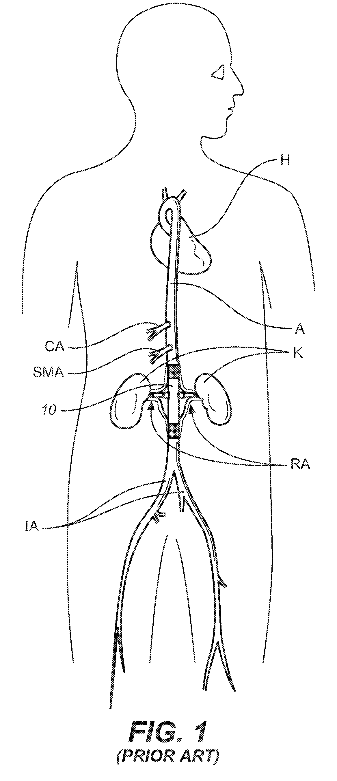
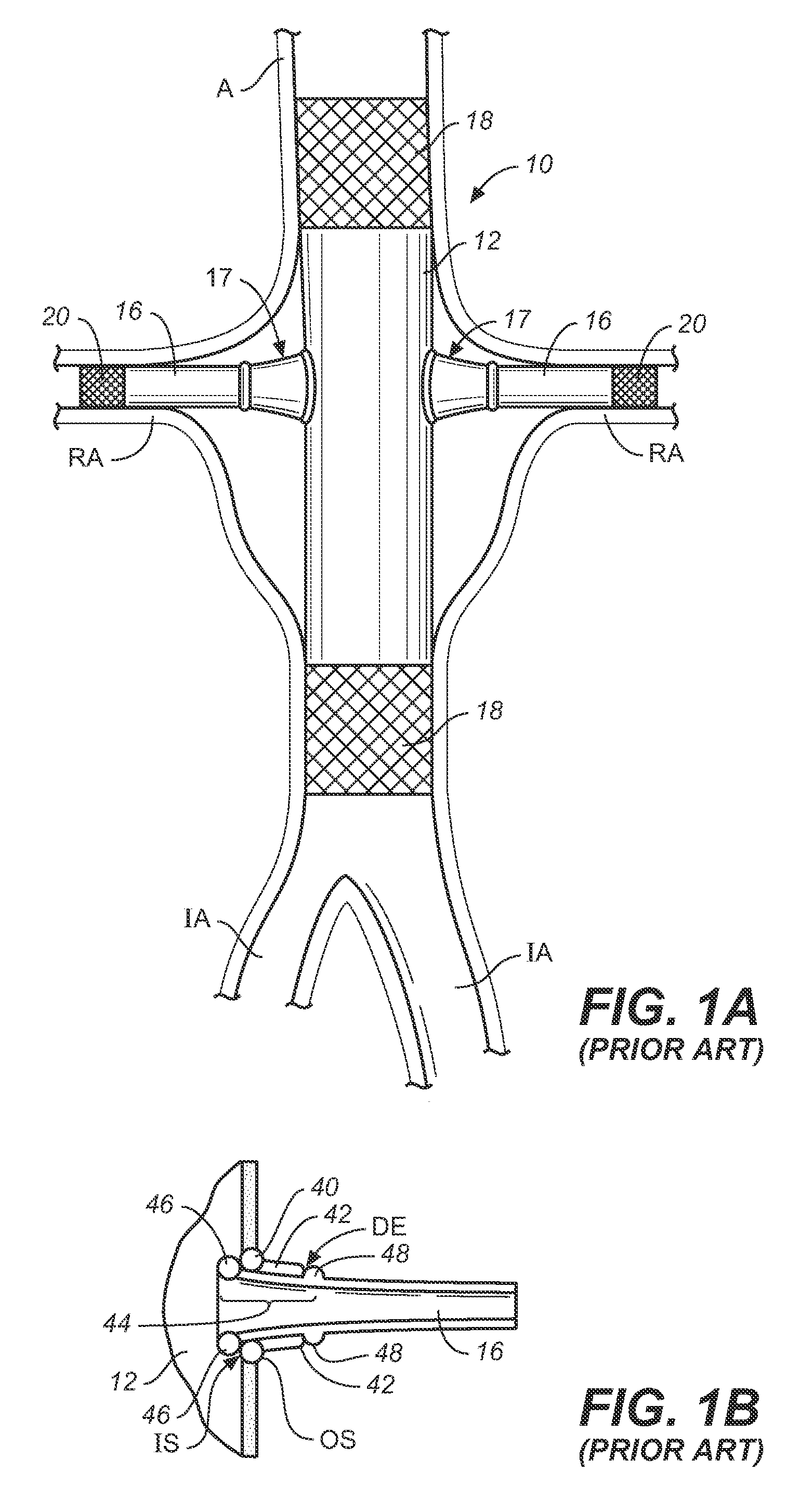
[0050]The prior art system described in the background has many common elements of the general structure and function of endoluminal grafting systems for branched anatomincal conduits according to the present invention. Several distinctions will illustrate the novel improvements therein.

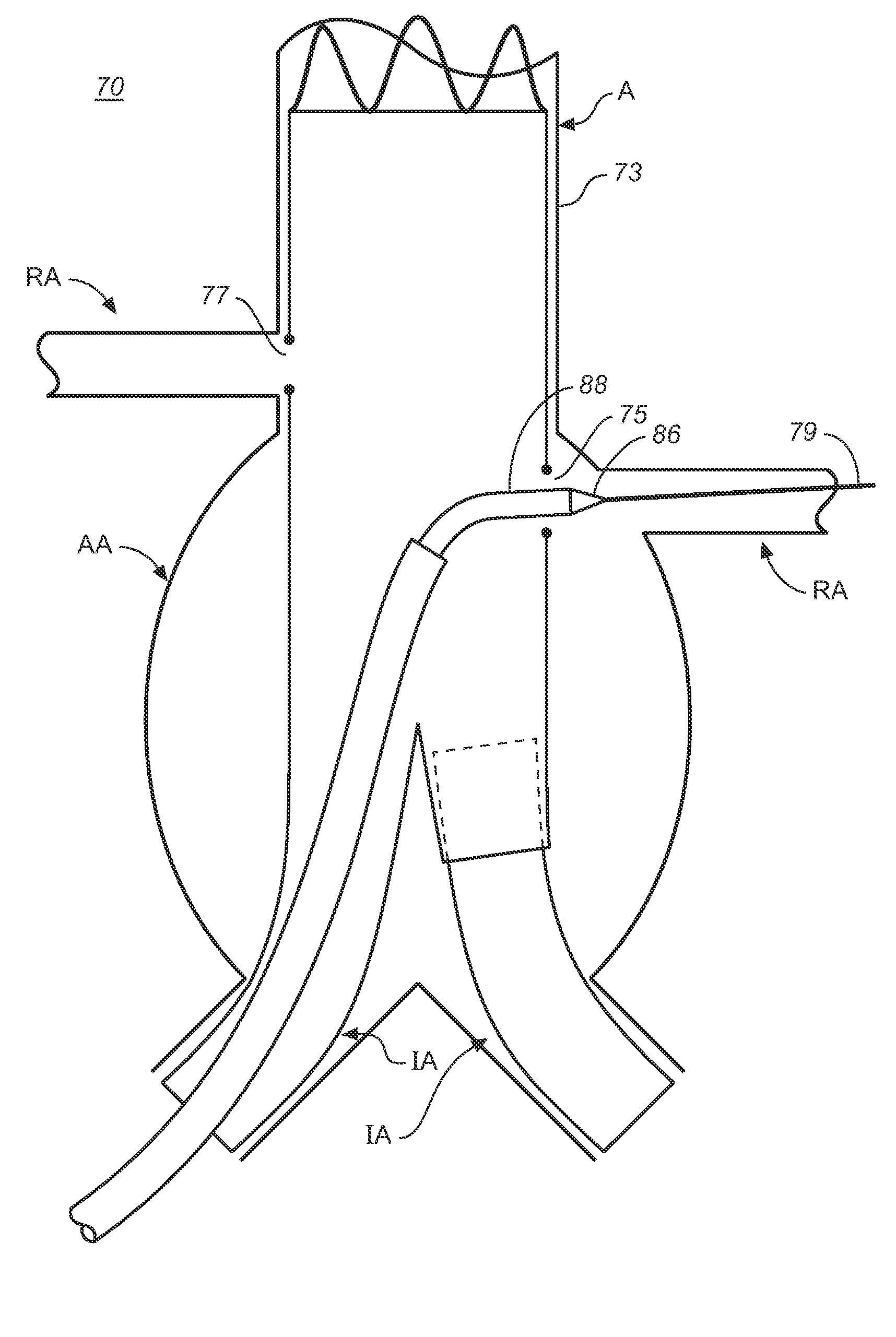
[0051]The primary graft or main stent-graft and branch graft deployment system 70 of FIGS. 2A-D is similar to the system 10 of FIGS. 1-1D except for various key features that would enable greater control, trackability, and maneuverability for both the primary and branch grafts even after partial deployment of the primary graft 72. As in system 10, the system 70 can include a deployed bifurcated primary graft 72 having a port or branch graft opening 75 or additional ports 77 as needed, a catheter system 76 including a retractable primary sheath, an outer tube with...


PUM


Abstract

A primary and branch graft deployment delivery system (70) comprises a primary graft (72) having a branch port opening or member (75), a retractable primary sheath containing the primary graft, an outer tube (60) within the retractable primary sheath and within the primary graft, an inner tube (61) within the outer tube, a cap (54 or 71) coupled to the inner tube and configured to retain at least a portion of a proximal area (73) of the primary graft in a radially compressed configuration. The system further comprises a branch graft (89) advanceable through the branch graft port member and further comprising a snap connector member (90) associated with the branch graft, the snap connector member being configured to frictionally engage the port member, the engagement of the snap connector to the port member forms a connection between the proximal end of the branch graft and the primary graft.

Description

FIELD OF THE INVENTION[0001]This invention relates generally to medical devices and procedures, and more particularly to a method and system of deploying a branch vessel graft in a vascular system.BACKGROUND OF THE INVENTION[0002]Prostheses for implantation in blood vessels or other similar organs of the living body are, in general, well known in the medical art. For example, prosthetic vascular grafts formed of biocompatible materials (e.g., Dacron or expanded, porous polytetrafluoroethylene (PTFE) tubing) have been employed to replace or bypass damaged or occluded natural blood vessels. A graft material supported by framework is known as a stent-graft or endoluminal graft. In general, the use of stent-grafts for treatment or isolation of vascular aneurysms and vessel walls which have been thinned or thickened by disease (endoluminal repair or exclusion) are well known. Many stent-grafts, are“self-expanding”, i.e., inserted into the vascular system in a compressed or contracted sta...

Claims


Application Information

Patent Timeline
Patent Type & Authority Applications(United States)
IPC IPC(8): A61F2/06
CPCA61F2/064A61F2/07A61F2/954A61F2002/061A61F2002/067A61F2220/0033A61F2002/30329A61F2002/9505A61F2002/9665A61F2220/0025A61F2/90A61F2002/075
Inventor WRIGHT, MICHAEL T.ARBEFEUILLE, SAMUELWIJERATNE, LALITHGREENAN, TREVOR
Owner MEDTRONIC VASCULAR INC
Why Eureka
Try Eureka