Circular LED panel light

Inactive Publication Date: 2008-07-17
LED FOLIO CORP
View PDF7 Cites 104 Cited by
  • Summary
  • Abstract
  • Description
  • Claims
  • Application Information

AI Technical Summary

Benefits of technology

[0006]Accordingly, embodiments of the invention are directed to an LED lighting device that substan

Problems solved by technology

However, light emitting diodes in the light emitting diode lighting panels used in lighting devices of various types are suscept

Method used


Image

  • Circular LED panel light
  • Circular LED panel light
  • Circular LED panel light

Examples


Embodiment Construction

[0040]Reference will now be made in detail to the preferred embodiments of the invention, examples of which are illustrated in the accompanying drawings. It will be apparent to those skilled in the art that various modifications and variations is made in the embodiments of the invention, the recessed can lighting device, without departing from its spirit or scope. Thus, it is intended that embodiments of the invention cover the modifications and variations of this invention provided they come within the scope of the appended claims and their equivalents. In the drawings, the thicknesses of layers and regions are exaggerated for clarity. Like reference numerals in the drawings denote like elements.

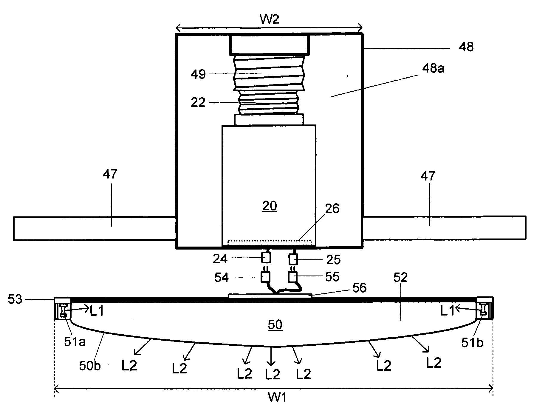
[0041]Installation of light emitting diode panels in recessed lighting devices typically requires for either redesign and modification of existing fixtures or the design of entirely new fixtures. Thus, a recessed lighting device with a light emitting diode panel that operates in recessed li...


PUM


Abstract

A lighting device comprising: a light emitting diode lighting panel having first and second opposing surfaces; light emitting diodes at a periphery of light emitting diode lighting panel for emitting light through the first surface; a reflective surface at the second surface of the light emitting diode lighting panel; and a power supply unit connected to the light emitting diode panel, the power supply having first and second ends, and electrical circuitry for converting alternating current to direct current between the first and second ends, wherein the first end is for insertion into the a socket.

Description

[0001]This invention claims the benefit of the Provisional Patent Application No. 60 / 880,393 filed with the U.S. Patent and Trademark Office on Jan. 16, 2007, which is hereby incorporated by reference in its entirety.BACKGROUND OF THE INVENTION[0002]The embodiments of the invention relate to a light emitting diode (LED) lighting device and more particularly, to an LED lighting device for a recessed can lighting system. Although embodiments of the invention are suitable for a wide scope of applications, they are particularly suitable for a light emitting diode panel in a recessed can.[0003]Various lighting devices are used to illuminate interior spaces. These include candelabras, chandeliers, track lighting and recessed cans. The latter are used when the lighting devices are to be hidden from view and otherwise unobtrusive. Most commonly, incandescent lighting is used in recessed cans.[0004]A recent trend in interior lighting is to replace incandescent bulbs with fluorescent bulbs. F...

Claims


Application Information

Patent Timeline
IPC IPC(8): F21V23/02F21V7/00H05B37/02H05B45/50
CPCF21V17/02Y02B20/383F21V21/002F21V21/03F21V21/14F21V21/22F21V21/32F21V23/02F21V23/06F21Y2101/02F21Y2103/022H01R33/94H01R33/9453H05B33/0803H05B33/0809Y02B20/19F21V17/14F21Y2103/33F21Y2115/10Y02B20/00Y02B20/30F21K9/23H05B45/30H05B45/357H05B45/50
Inventor KIM, STEVEN
Owner LED FOLIO CORP
Why Eureka
Try Eureka