Scuff plate

a technology of scuff plate and scuff plate, which is applied in the field of scuff plate, can solve the problems of complex process of producing scuff plate, inability to visually recognize wire harness, and exposure to rain water, and achieve excellent rigidity, suppress damage of light guide member, and excellent design

Inactive Publication Date: 2008-07-17
TOYODA GOSEI CO LTD
View PDF12 Cites 24 Cited by
  • Summary
  • Abstract
  • Description
  • Claims
  • Application Information

AI Technical Summary

Benefits of technology

[0021]In the case where the screen member made of metal is used, metallic luster resulting from the screen member can be visually recognized through the light guide member. Therefore, the scuff plate of the invention having the above feature (1) is more excellent in design.
[0022]The scuff plate of the invention having at least one of the above features (2) and (3) is excellent in rigidity to suppress damage of the light guide member, and also is excellent in design.
[0023]The scuff plate of the invention having the above feature (4) can cause the luminous recess to shine uniformly and bright, and therefore is excellent in design.
[0024]The scuff plate of the invention having the above feature (5) can suppress an uneven shining developing on the side surface of the light guide member, and therefore is excellent in design.
[0025]The scuff plate of the invention having the above feature (6) can cause the luminous recess to shine bright while suppressing an uneven shining developing on the side surface of the light guide member, and therefore is excellent in design.
[0026]The scuff plate of the invention having the above feature (7) can cause the light guide member to shine in a desired color, and therefore is excellent in design, and besides this scuff plate can be produced at a low cost.

Problems solved by technology

Therefore, in case the wire harness is installed along the outside of this case, it is thought that the wire harness will not be visually recognized through the light guide member.
The scuff plate is provided at the boundary between the interior and exterior of a passenger compartment of the vehicle, and therefore can often be exposed to rain water.
Therefore, in this case, the process of producing the scuff plate becomes complicated, and the cost of the scuff plate increases.
Therefore, the conventional scuff plates have a problem that the excellent design and the reduced production cost are not compatible.

Method used


Image

  • Scuff plate
  • Scuff plate
  • Scuff plate

Examples


first embodiment

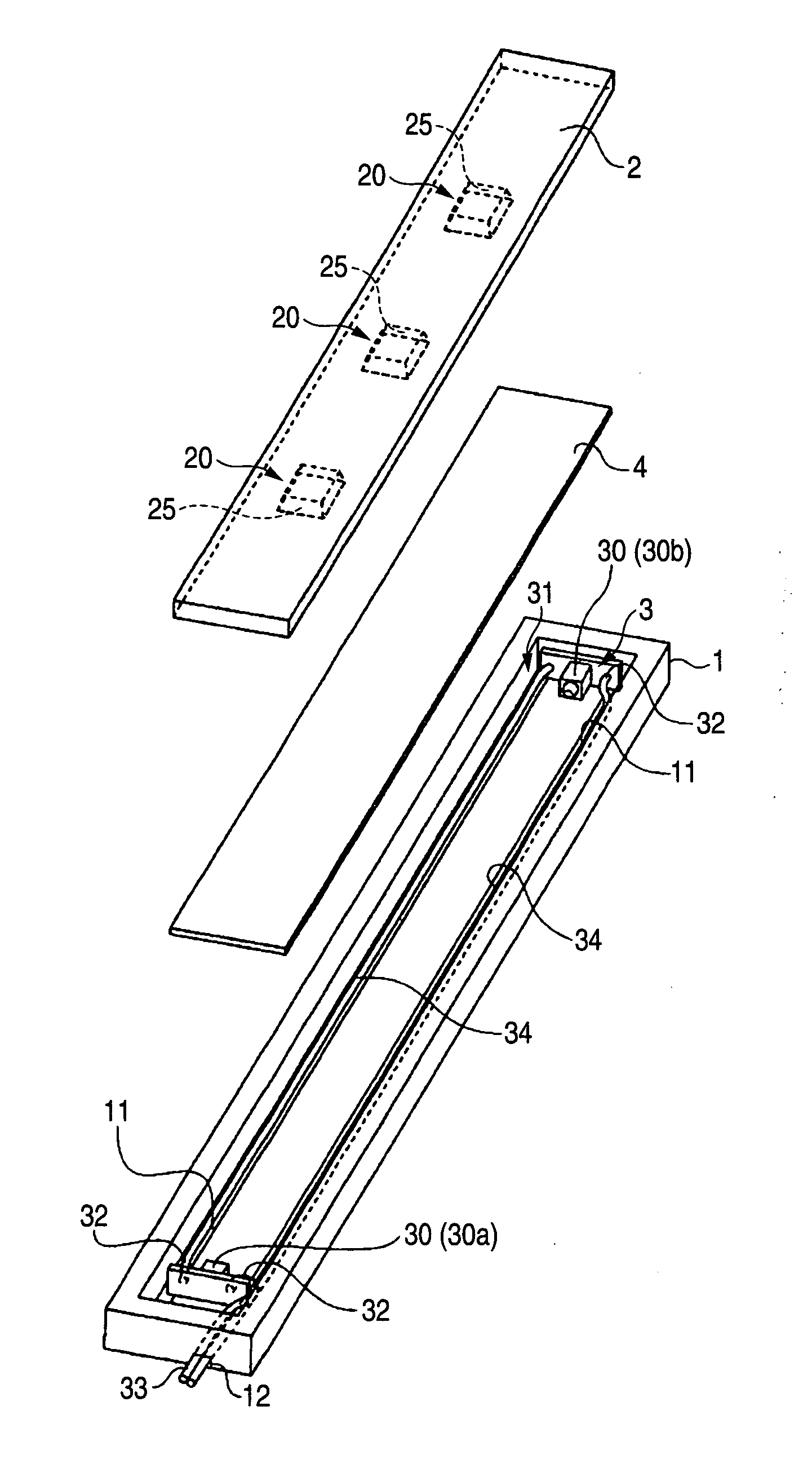
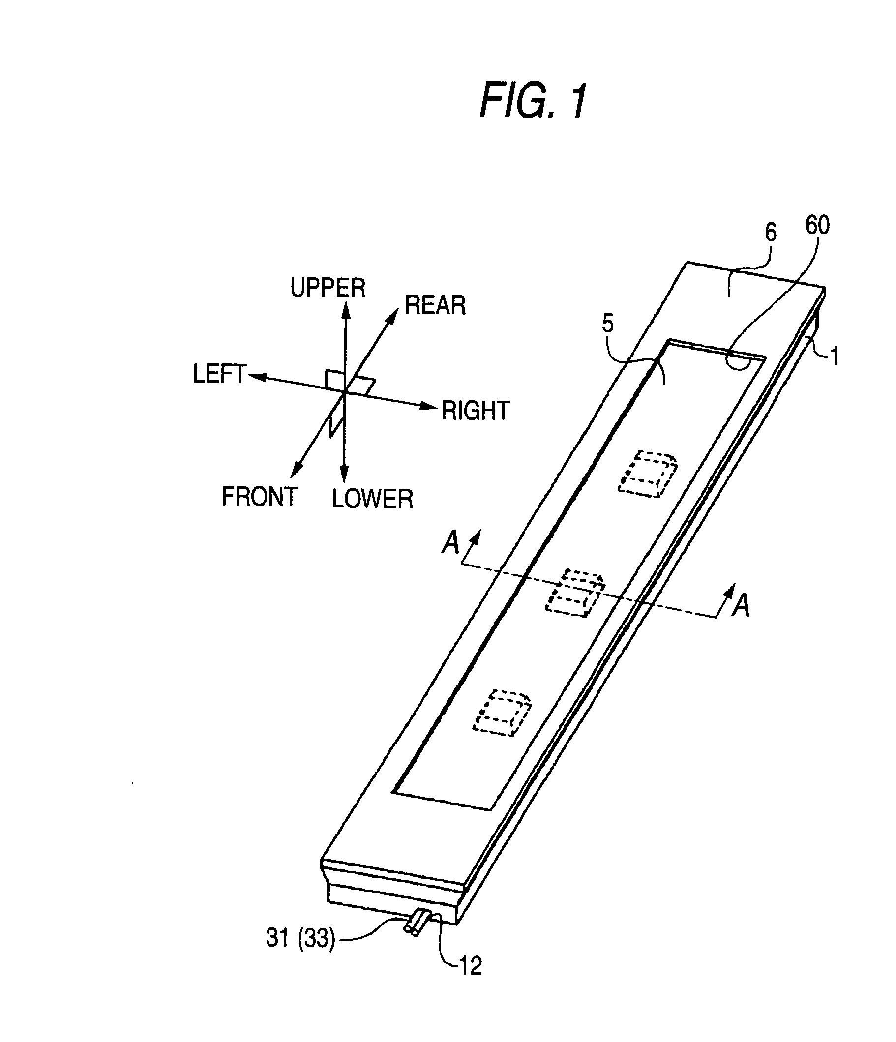
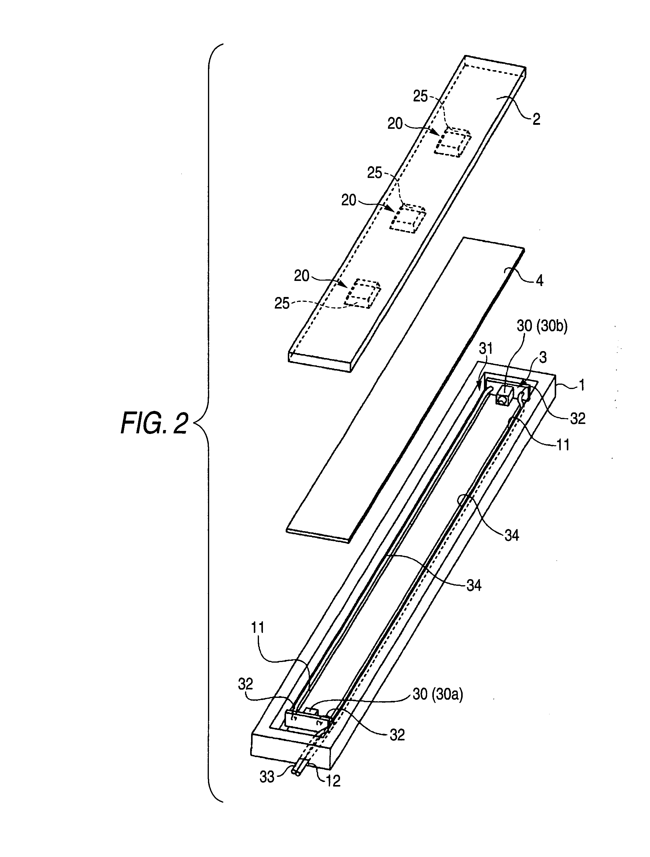
[0051]A scuff plate of a first embodiment has the above feature (1). FIG. 1 is a perspective view schematically showing the scuff plate of the first embodiment. FIG. 2 is an exploded perspective view schematically showing a case, a light guide member and a light source unit of the scuff plate of the first embodiment. FIG. 3 is a schematic cross-sectional view of the scuff plate of the first embodiment taken along the line A-A of FIG. 1. In the following description of the first embodiment, the upper, lower, left, right, front and rear sides correspond respectively to the upper, lower, left, right, front and rear sides in FIG. 1.

[0052]The scuff plate of the first embodiment comprises the case 1, the light guide member 2, the light source unit 3, a screen member 4, a protective member 5, and a high-strength protective member 6.

[0053]The case 1 is made of a resin, and has an elongated box-like shape with an open top. As shown in FIGS. 2 and 3, two groove portions 11 each in the form of...

second embodiment

[0065]A scuff plate of a second embodiment has the above features (1) to (3). FIG. 4 is a schematic cross-sectional view similar to FIG. 3 but showing the scuff plate of the second embodiment.

[0066]The scuff plate of the second embodiment is identical to the scuff plate of the first embodiment except that a light guide member 2 has a different shape. In the scuff plate of the second embodiment, an inward portion 21 of an obverse surface (upper surface in FIG. 4) of the light guide member 2 disposed inwardly of an outer peripheral portion 22 thereof is depressed with respect to the outer peripheral portion 22. Namely, the obverse surface of the light guide member 2 assumes a picture frame-like shape. A boundary portion 23 between the inward portion 21 and the outer peripheral portion 22 has a slanting shape such that a depression height thereof gradually changes.

[0067]A protective member 5 is held against the outer peripheral portion 22 of the light guide member 2. Therefore, in the ...

third embodiment

[0070]A scuff plate of a third embodiment has the above features (1) and (2). The scuff plate of the third embodiment is identical to the scuff plate of the second embodiment except that a light guide member has a different shape. FIG. 5 is a schematic cross-sectional view similar to FIG. 3 but showing the scuff plate of the third embodiment.

[0071]In the scuff plate of the third embodiment, an obverse surface (upper surface) of the light guide member 2 is flat. An upper end (edge) surface 13 of a case 1 projects upwardly from the obverse surface of the light guide member 2. A protective member 5 is held against the upper end surface 13 of the case 1. Therefore, in the scuff plate of the third embodiment, part of the case 1 serves as a spacer, and the whole of the obverse surface of the light guide member 2 is spaced from the reverse surface of the protective member 5. In the scuff plate of the third embodiment, the reverse surface of the protective member 5 is spaced from the obvers...


PUM


Abstract

Luminous surfaces 25 of a concave-convex shape are formed on a light guide member 2 of a scuff plate, and a screen member 4 made of a non-transparent material is disposed between the light guide member 2 and a wire harness 31 of the scuff plate. The light guide member 2 luminously displays a design in a three-dimensional manner, and also the wire harness 31 will not be visually recognized through the light guide member 2, and therefore the design is enhanced.

Description

BACKGROUND OF THE INVENTION[0001]1. Field of the Invention[0002]This invention relates to a scuff plate for a vehicle.[0003]2. Description of the Related Art[0004]A scuff plate is a member for protecting an edge portion (side sill) of a door opening formed in a vehicle. In recent years, there have been proposed scuff plates which luminously display a design such as characters (see, for example, Patent Literatures 1 and 2)[0005]A scuff plate disclosed in Patent Literature 1 comprises a light guide member made of a transparent material, a light source, and a metal plate placed on an upper surface of the light guide member and including light transmission holes having respective predetermined shapes. In this scuff plate, light emitted from the light source enters the light guide member, and then goes to the exterior through the light transmission holes. Therefore, a design corresponding to the shapes of the light transmission holes is displaced on the scuff plate in a luminous manner. ...

Claims


Application Information

Patent Timeline
Patent Type & Authority Applications(United States)
IPC IPC(8): B60Q1/32
CPCB60Q3/0216B60Q1/323B60Q3/217B60Q1/325
Inventor KAMIYA, TAKAYUKIHIGUCHI, YASUYUKITAKEDA, KAZUOTOTANI, CHIHARUOBA, TATSUYAINUI, SHUJI
Owner TOYODA GOSEI CO LTD
Why Eureka
Try Eureka