
Golf club head groove configuration

a golf club and groove technology, applied in the field of golf clubs, can solve problems such as inconsistency along the length of the groove, and achieve the effects of tightening the tolerance, tightening the draft angle, and increasing the production ra

Active Publication Date: 2008-07-17
ACUSHNET CO
View PDF21 Cites 31 Cited by
  • Summary
  • Abstract
  • Description
  • Claims
  • Application Information

AI Technical Summary

Benefits of technology

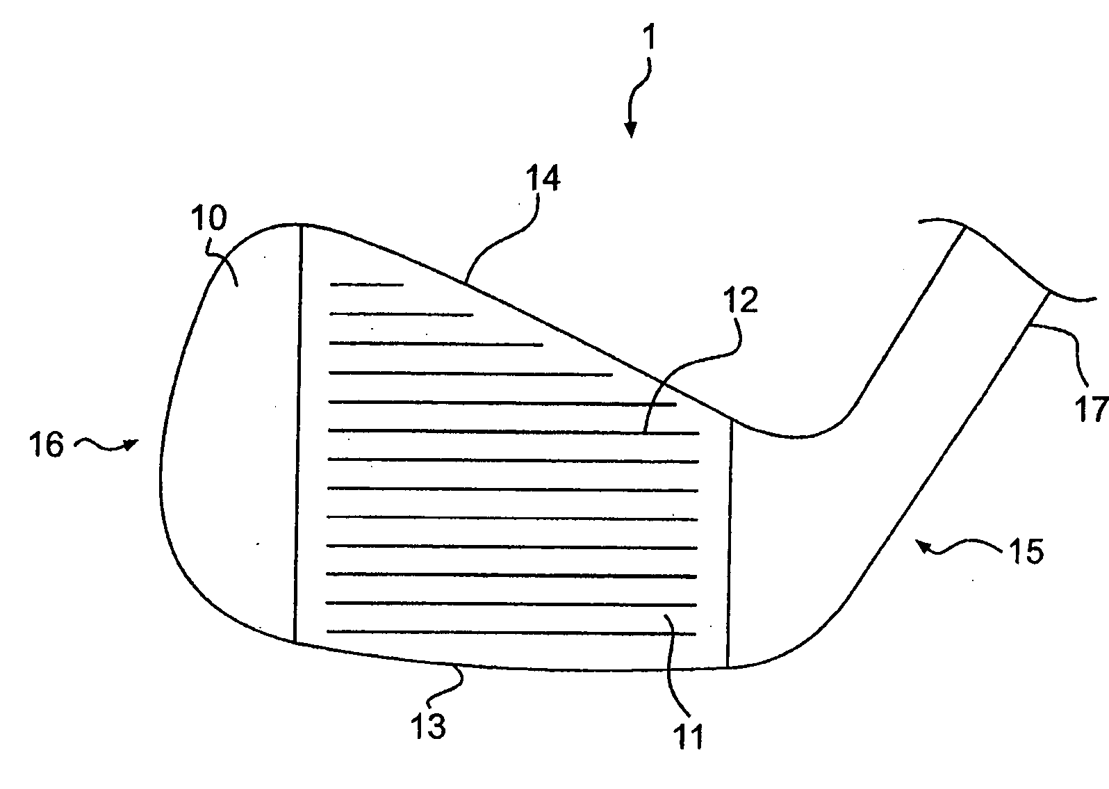
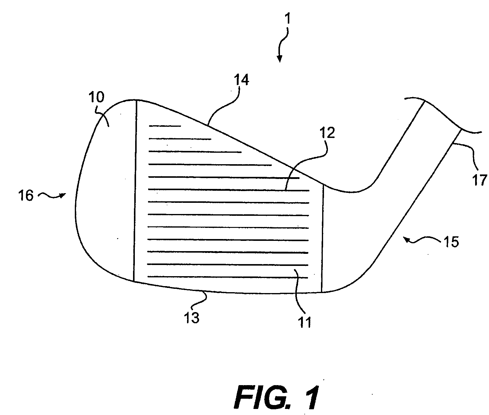
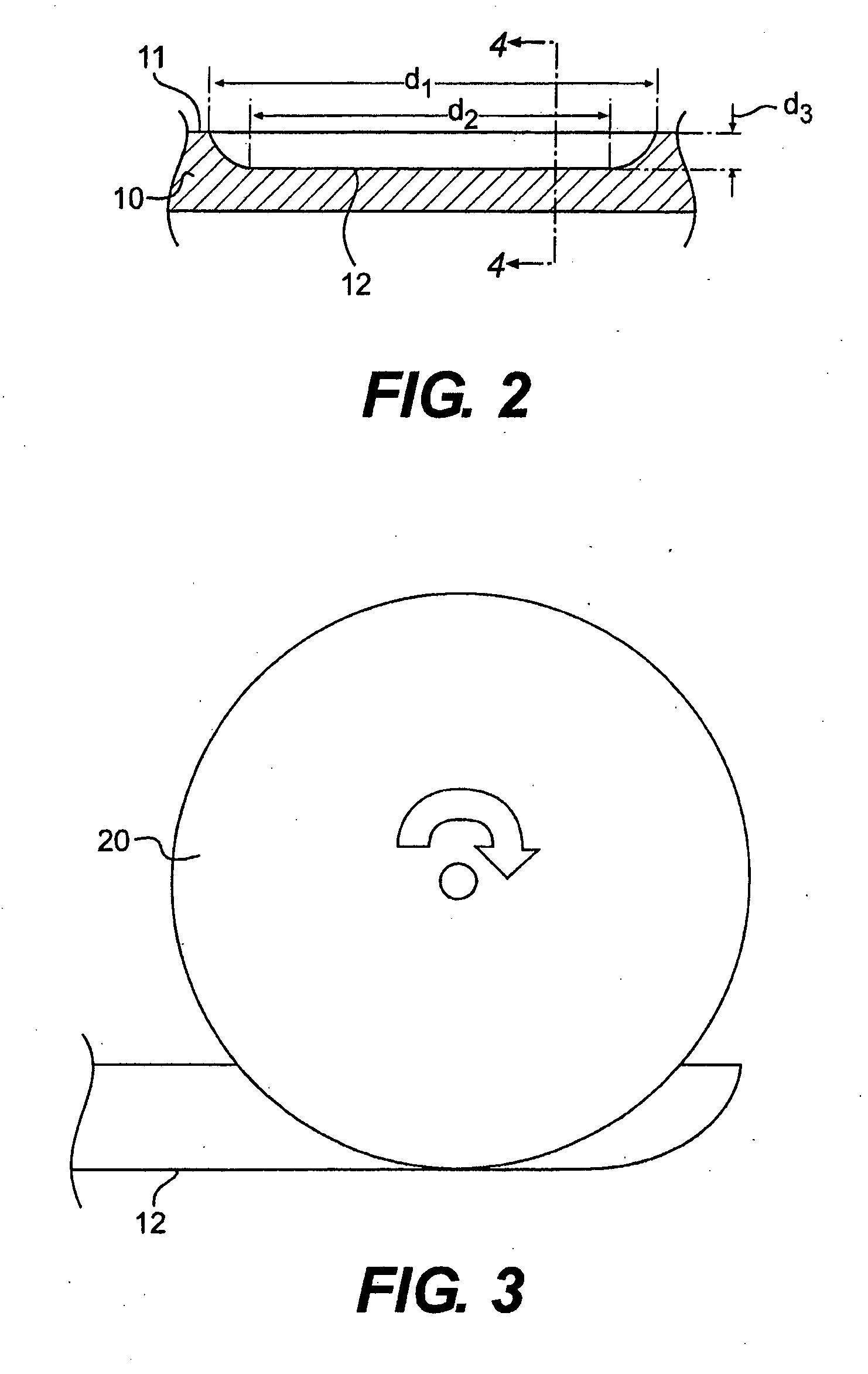
[0012]Preferably, the grooves are angled or otherwise ramped from their maximum depth into the face to the face surface at the groove ends. This helps facilitate cleaning sand, dirt, and other debris the grooves. This may be characterized in a variety of manners. For example, the maximum depth distance of the groove (that is, the non-ramped portion of the groove) versus the overall length of the groove. In one preferred embodiment, the overall groove length is at least 0.25 inch longer than the overall groove length. As another example, the grooves may be radiused at toe and heel portions of the golf club head, a preferred radius range being from 0.125 inch to 5 inches. The maximum depth of the grooves may be about 0.02 inch deep at a geometric center of the face.
[0013]The grooves of the present invention preferably are formed by spin milling or fly cutting. Forming the grooves in this manner allows for tighter draft angles, increases the rate of production, and allows for tighter tolerances than casting or forging. Preferably, the draft angle of the inventive grooves is between about 0.5° and 12°. The grooves may be formed by a round cutter, preferably having a diameter from ⅜ inch to ¾ inch. A preferred draft angle range is from about 0.5° to 12°.
[0014]The surface of the club face may be textured or roughened. Providing a textured strike face allows the golfer to apply more friction to the ball during use, allowing the golfer to put more spin on the ball and have greater control of the ball. Preferably, the surface has a substantially uniform textured surface with a roughness greater than 40 Ra.

Problems solved by technology

Machining grooves in the face after it has been milled beneficially saves them from being effected by any face post-manufacturing processes, which can adversely effect, for example, the groove-face interface, making it inconsistent along the length of the groove.

Method used


Image

  • Golf club head groove configuration
  • Golf club head groove configuration
  • Golf club head groove configuration

Examples


Embodiment Construction

[0028]Other than in the operating examples, or unless otherwise expressly specified, all of the numerical ranges, amounts, values and percentages such as those for amounts of materials, moments of inertias, center of gravity locations, loft and draft angles, and others in the following portion of the specification may be read as if prefaced by the word “about” even though the term “about” may not expressly appear with the value, amount, or range. Accordingly, unless indicated to the contrary, the numerical parameters set forth in the following specification and attached claims are approximations that may vary depending upon the desired properties sought to be obtained by the present invention. At the very least, and not as an attempt to limit the application of the doctrine of equivalents to the scope of the claims, each numerical parameter should at least be construed in light of the number of reported significant digits and by applying ordinary rounding techniques.

[0029]Notwithsta...


PUM


Abstract

The present invention is directed to a golf club head with an improved striking surface. The grooves are machined into the strike surface with tight tolerances. The grooves have sharp edges, radiused ends, and a draft angle between about 2° and 12°. The striking face is machined such that it has a uniform texture with a roughness of more than 40 Ra. The grooves may contain a plurality of portions, including a radiused or angled portion, a portion having substantially parallel walls, a portion having a v-shape, and a curved portion. The grooves may also be characterized by various dimensions, including draft angle, inclusive side wall angle, width, depth, cross-sectional area, spacing, and pitch ratio. Preferred values for these dimension are provided.

Description

CROSS-REFERENCE TO RELATED APPLICATIONS[0001]This is a continuation-in-part of U.S. patent application Ser. No. 11 / 711,096 filed on Feb. 27, 2007, now pending, which is a continuation-in-part of U.S. patent application Ser. No. 10 / 902,064 filed on Jul. 30, 2004, now U.S. Pat. No. 7,273,422, which are incorporated herein by reference in its entirety.[0002]This application claims the benefit of U.S. Provisional Patent Application No. 60 / 528,708 filed on Dec. 12, 2003, which is incorporated herein by reference in its entirety.BACKGROUND OF THE INVENTION[0003]1. Field of the Invention[0004]The present invention relates to golf clubs. In particular, the present invention relates to a golf club head having an improved striking surface.[0005]2. Description of the Related Art[0006]Golf club heads come in many different forms and makes, such as wood- or metal-type, iron-type (including wedge-type club heads), utility- or specialty-type, and putter-type. Each of these styles has a prescribed ...

Claims


Application Information

Patent Timeline
Patent Type & Authority Applications(United States)
IPC IPC(8): A63B53/04
CPCA63B53/04A63B53/047A63B2053/0445A63B53/0445A63B60/00
Inventor GILBERT, PETER J.CLAUSEN, KARL A.
Owner ACUSHNET CO
Learn More