
Virtual machine system

a virtual machine and machine technology, applied in the field of virtual machine systems, can solve the problems of increasing the overhead of io processing, unable to specify the io band according to the priority of services run on the virtual server, and certain limitations of software components such as vmm, so as to achieve the effect of curbing the overhead of performan

Inactive Publication Date: 2008-07-17
HITACHI LTD
View PDF14 Cites 25 Cited by
  • Summary
  • Abstract
  • Description
  • Claims
  • Application Information

AI Technical Summary

Benefits of technology

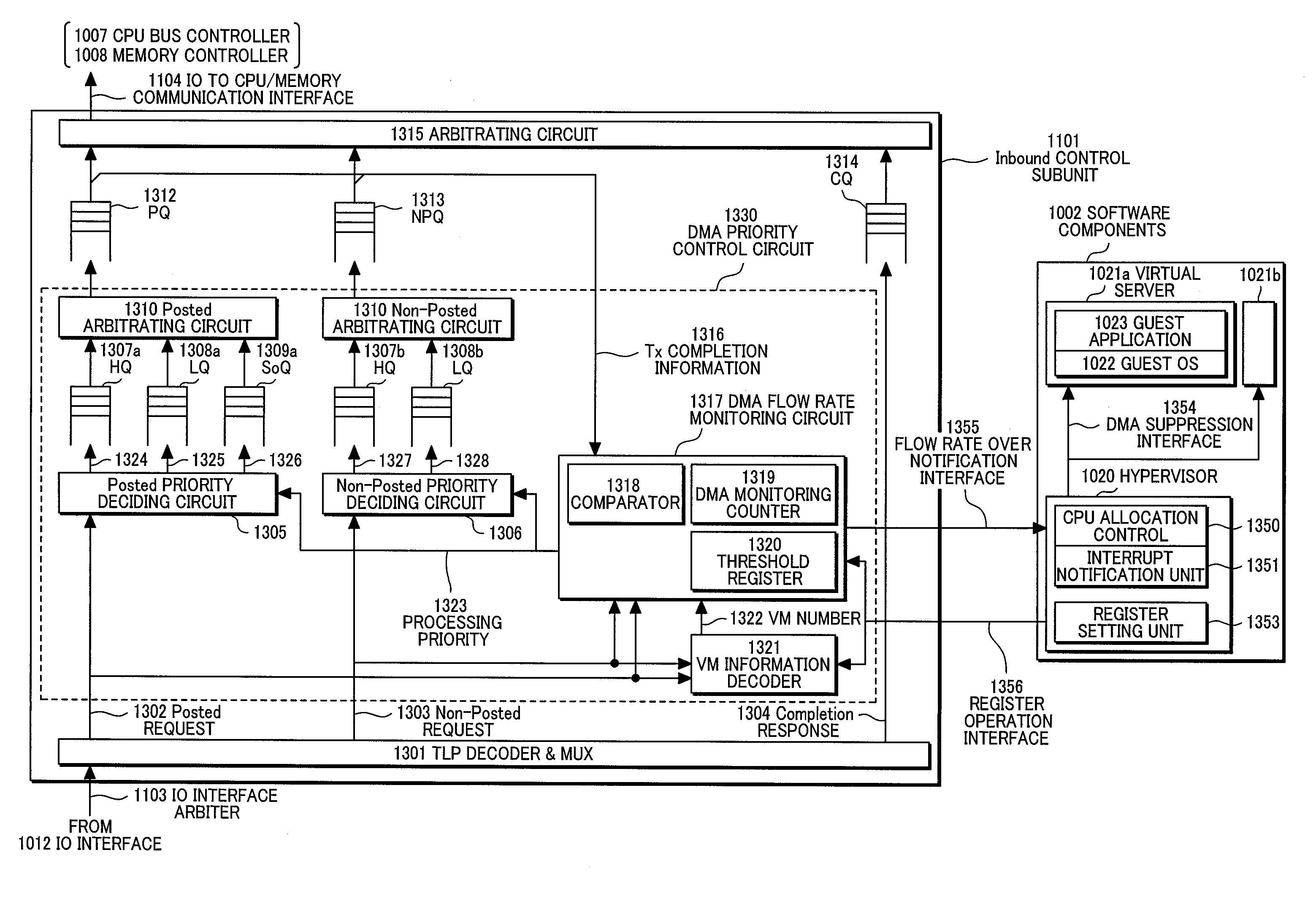
The present invention provides a machine system that can control the access of input / output (IO) devices among virtual servers with priority and quality of service (QoS) in mind. This is done by monitoring the processing status of each virtual server and comparing it with a threshold value set in advance. This allows for the prioritization of processing requests from virtual servers, reducing performance overhead during shared use of the IO devices. Overall, the invention enables efficient and effective arbitration of IO accesses and band control based on the priority of virtual servers.

Problems solved by technology

However, the related art disclosed in U.S. Pat. No. 6,496,847 does not control IO accesses among virtual servers with priority and QoS (Quality of Service) in mind, so that IO bands cannot be specified according to the priority of services run on the virtual servers.
Placing certain limitations on IO accesses by software components such as VMM could not be said to be sufficient in terms of future wider bands of IO devices because performance overhead on IO processing increases.

Method used


Image

  • Virtual machine system
  • Virtual machine system
  • Virtual machine system

Examples


first embodiment

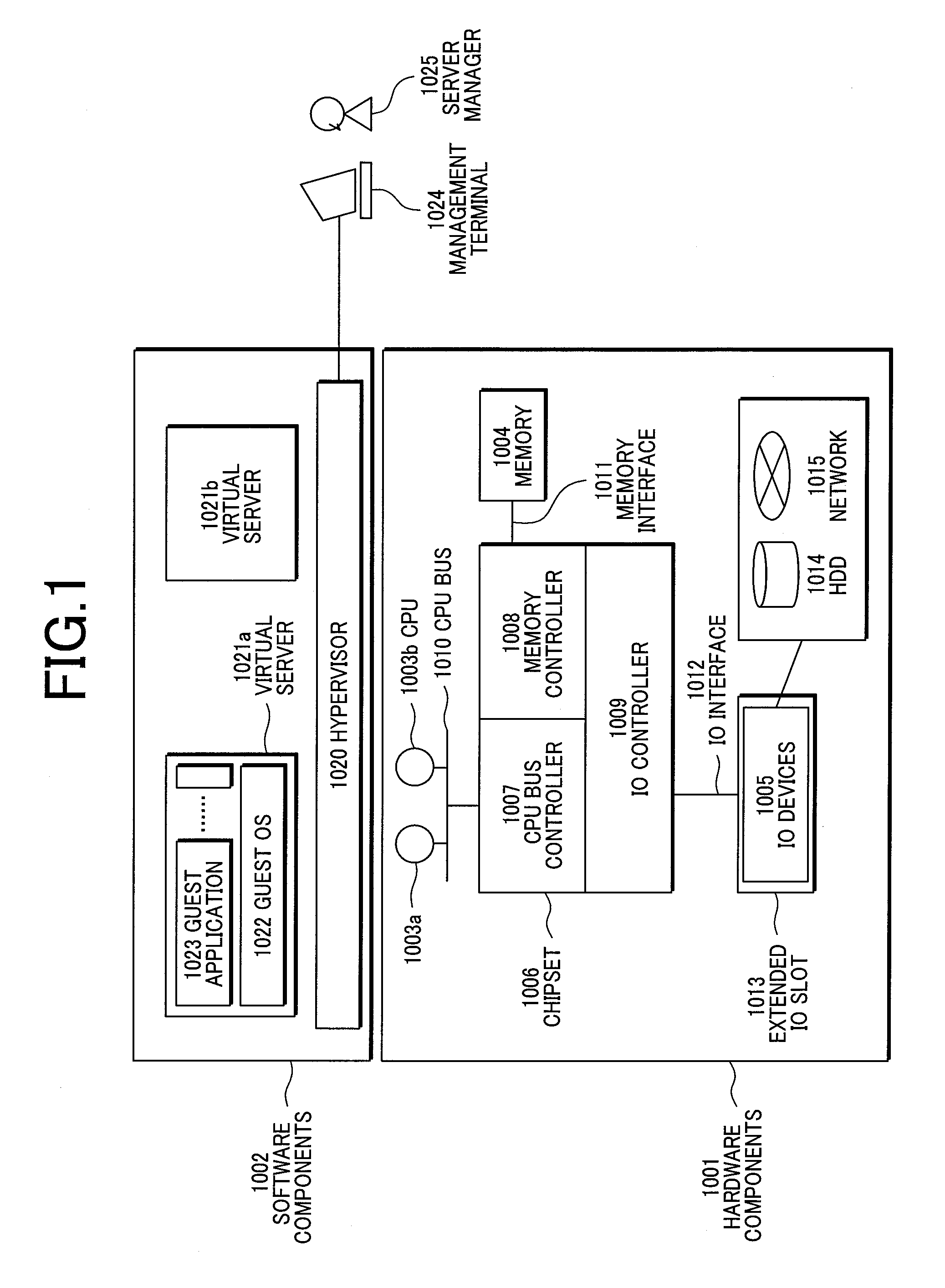
[0030]FIG. 1 shows an example of the structure of a virtual machine system that embodiments including a first embodiment presuppose. The computer mainly comprises hardware components 1001 and software components 1002.

[0031]The hardware components 1001 include CPUs 1003a and 1003b as processing units, a memory 1004 as a storing unit, and IO devices 1005, which are mutually connected via a chipset 1006. The chipset 1006 is connected with CPUs 1003a and 1003b through a CPU bus 1010, with the memory 1004 through a memory interface 1011, and with the IO devices 1005 through an IO interface 1012 and an extended IO slot 1013. The IO devices 1005 are further connected with HDD (Hard Disk Drive) 1014 or a network 1015.

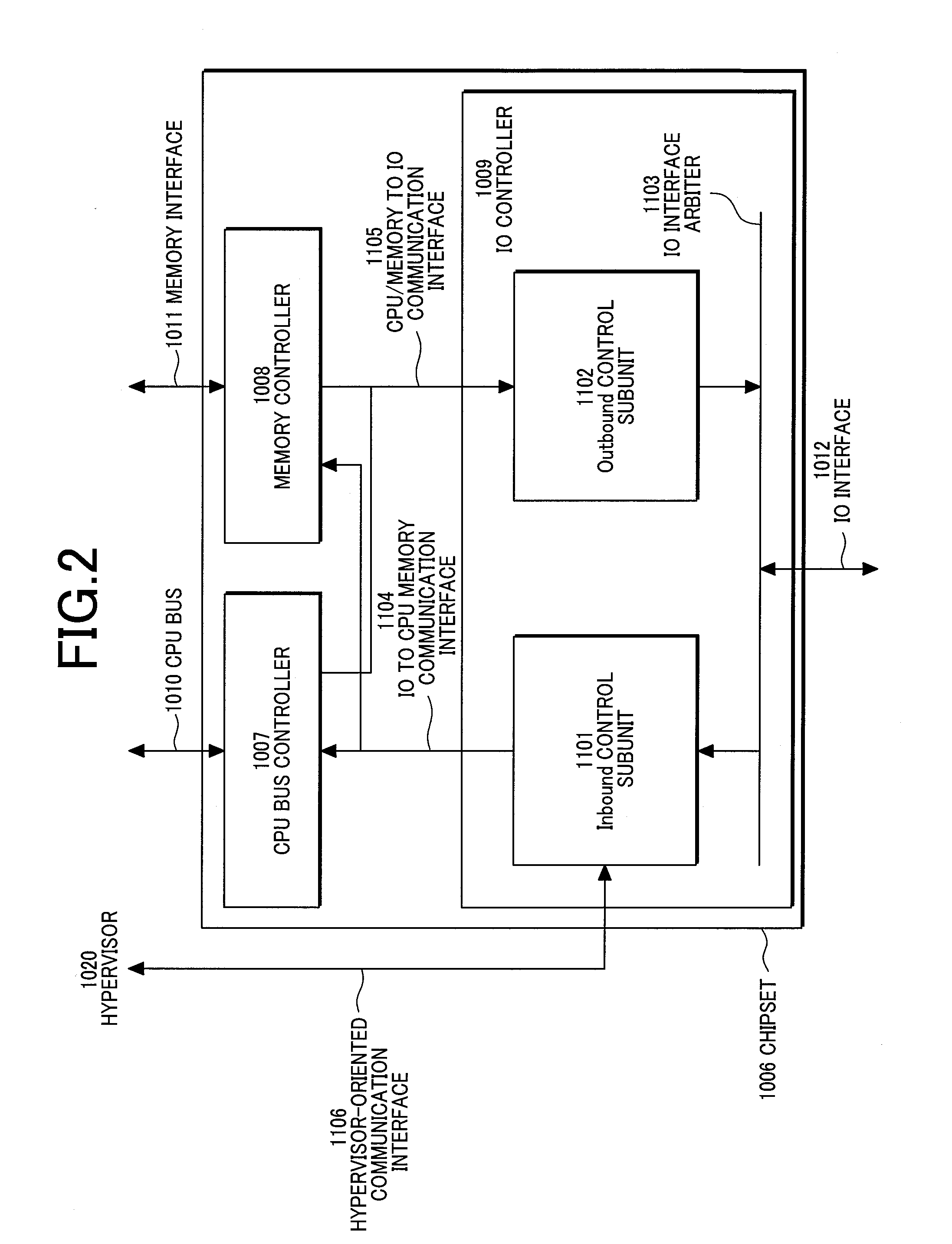
[0032]The chipset 1006 is internally divided into a CPU bus controller 1007, a memory controller 1008, and an IO controller 1009, which respectively control the CPU bus 1010, memory interface 1011, and IO interfaces 1012, which are connected with the chipset. Although the numbe...

second embodiment

[0105]The following a second embodiment. This embodiment achieves a capping function to prohibit DMA requests consuming more IO band than specified by allocating virtual channels (VC) to virtual servers.

[0106]FIG. 11 shows the structure of main units of the second embodiment of the present invention, that is, the internal structure of the inbound control subunit 1101 and the software components 1002. The inbound control subunit 1101 allocates one VC to one virtual server to make the control structure of Tx processing independent for each of virtual servers. Therefore, the unit 1101 internally includes a VC-specific inbound TLP processing circuits 2110b and 2110c, as well as a VC MUX 2103, and an inter-VC arbitrating circuit 2102, and VM information decoder 2105.

[0107]The VM information decoder 2105 receives TC# (Traffic Class) 2104 of the header of Tx received from the IO interface arbiter 1103, and then locates VC# 2107 according to information of the W#-VC# correspondence table 21...

third embodiment

[0113]The following describes a third embodiment. In this embodiment, virtual-server-specific IO band control is performed not in IO controllers but in IO devices.

[0114]FIG. 13 shows an internal structure of an IO device 1005d in this embodiment. FIG. 13 assumes NIC (Network Interface Card), which is connected to the outside through the IO interface 1012 and the network 1015.

[0115]The IO device 1005d includes an arbitrating circuit 1315d for PQ 1312d, NPQ 1313d, and CQ 1314d that transmit Tx to the IO interface 1012, and includes PQ 1312e, NPQ 1313e, and CQ 1314e that receive Tx from the IO interface 1012. It also includes N / W packet transmission 230 that transmits packets to the network 1015, and N / W packet reception 2303 that receives packet.

[0116]In this embodiment, a DMA capping control circuit 2101d is provided as a component that controls IO bands. The DMA capping control circuit 2101d internally includes a DMA flow rate monitoring circuit 1317d and an AND element that decides...


PUM


Abstract

The present invention provides a machine system that enables the arbitration of IO accesses and band control based on the priority of virtual servers while curbing performance overhead during IO sharing among the virtual servers. A virtual machine system including a CPU, a memory, and an IO interface includes a hypervisor that generates plural virtual servers, and an IO controller that controls the IO interface. The IO controller includes: a DMA receiving unit that receives DMA requests from the IO interface; a decoder that decodes received DMA requests and locates the corresponding virtual servers; a DMA monitoring counter that monitors DMA processing status for each of the virtual servers; a threshold register set in advance for each of the virtual servers; and a priority deciding unit that compares the DMA monitoring counter and the value of the threshold register, and based on processing priority obtained as a result of the comparison, decides the priority of processing of the received DMA requests.

Description

CLAIM OF PRIORITY[0001]The present application claims priority from Japanese Application JP 2007-008220 filed on Jan. 17, 2007, the content of which is hereby incorporated by reference into this application.BACKGROUND OF THE INVENTION[0002]The present invention relates to a virtual machine system, and technology for sharing IO (Input / Output) devices among plural virtual servers.[0003]A virtual machine system is widely known in which plural virtual servers are configured on one computer, and an operating system (OS) is individually run on each server. To run a large number of virtual severs in a virtual machine system, IO devices must be shared among the virtual servers.[0004]As technology for sharing IO devices among virtual servers, a method of emulating the IO devices by software is known. A method disclosed by U.S. Pat. No. 6,496,847 provides virtual IO devices for an OS on a virtual server. A virtual machine monitor (hereinafter referred to as VMM) receives accesses to virtual I...

Claims


Application Information

Patent Timeline
Patent Type & Authority Applications(United States)
IPC IPC(8): G06F13/28
CPCG06F13/36G06F13/28
Inventor MORIKI, TOSHIOMIUEHARA, KEITAROTSUSHIMA, YUJI
Owner HITACHI LTD
Learn More