Clip

a clip and clip technology, applied in the field of clips, can solve the problems of reducing the efficiency of the trim removal operation and the difficulty of using the securing shoulders, and achieve the effects of reducing the rigidity of the clip, increasing the thickness of the clip, and increasing the size of the clip

Active Publication Date: 2008-07-24
PIOLAX CO LTD
View PDF2 Cites 9 Cited by
  • Summary
  • Abstract
  • Description
  • Claims
  • Application Information

AI Technical Summary

Benefits of technology

[0016]Here, when the recessed portions are formed in the width direction entire areas of the side walls of the base body or in the width direction entire areas of the elastic arms, the rigidity of the clip is lowered. This means that the thickness of the clip must be increased and thus the size of the clip must be increased. However, according to the third aspect of the invention, since each of the recessed portions is formed such that a portion thereof is left in the width direction of the side wall of the base body or the elastic arm, not only the rigidity of the recessed portion forming portion can be maintained but also the size of the clip can be reduced.
[0017]According to the fourth aspect of the invention, since the respective recessed portions are formed such that the left portions thereof alternate each other, on both sides, there can be obtained a uniform engagement state between the recessed portions and projecting portions. This makes it possible to positively hold the clip on the boss portion side of the mounting part. Also, when engaging the clip with the boss portion of the mounting part provisionally, since there can be eliminated the need to pay attention to the engaging direction of the clip, the efficiency of the engaging operation can be enhanced.
[0018]According to the fifth aspect of the invention, the recessed portions and projecting portions overlap each other in part in a state where the mounting part is fixed to the panel. Therefore, when an expected pull-out force is applied to the mounting part, or when the base body of the clip is pulled out from the mounting hole of the panel, since the recessed portions and projecting portions are guided by their partially overlapping state, they can be engaged with each other positively, whereby a high pull-out load can be secured stably all the time.

Problems solved by technology

In this case, when trying to pull out the boss portion of the trim from the mounting hole of the car body panel, the securing shoulders are shaved off by the hole edge of the mounting hole, which makes it difficult to use the securing shoulders again; and, on the other hand, when the projecting amounts of the securing shoulders are increased without changing the angles thereof, the inserting forces of the securing shoulders with respect to the mounting hole of the car body panel become too high, which raises a fear that the efficiency of the trim removing operation can be lowered.

Method used


Image

  • Clip
  • Clip
  • Clip

Examples


Embodiment Construction

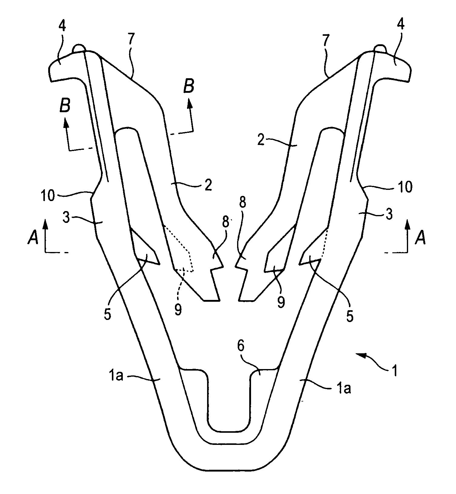
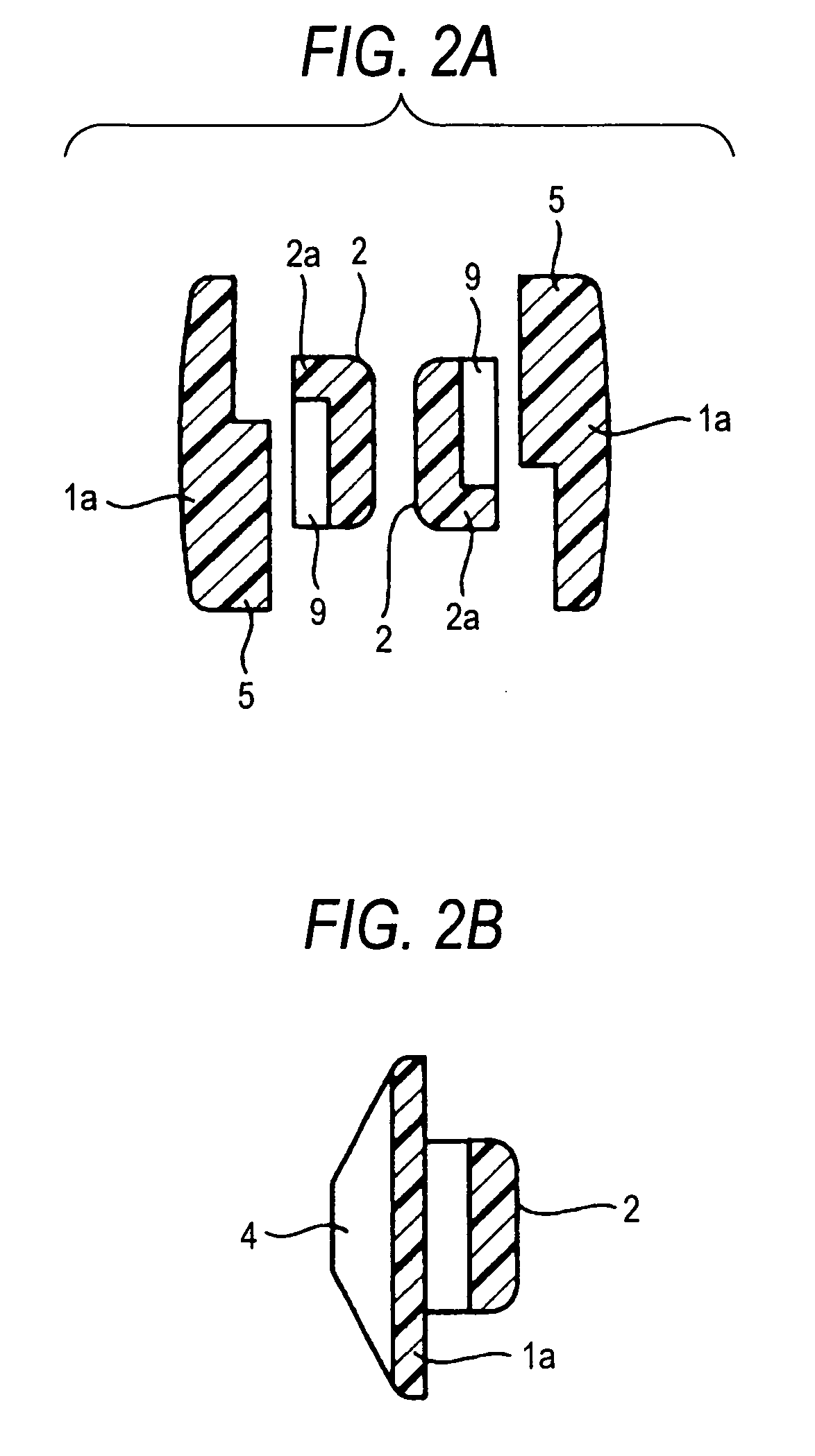
[0027]According to the invention, there is provided a clip which is used to fix a mounting part with a boss portion provided on and suspended perpendicularly from the back surface thereof to a panel with a mounting hole formed therein, and also which includes: a base body having a U-shaped section and including a pair of mutually opposed side walls; a pair of elastic arms respectively extended from the inner surfaces of their associated side walls of the base; and, a pair of securing shoulders respectively provided on and projected from the outer surfaces of their associated side walls of the base body, each securing shoulder having a tapered surface portion. In the present clip, in the inner surfaces of the leading end portions of the pair of elastic arms, there are formed engaging pawl portions engageable with an engaging portion formed in the boss portion; in one of the inner surfaces of the side walls of the base body and the outer surfaces of the elastic arms corresponding to t...


PUM


Abstract

A clip for fixing a mounting part with a boss portion provided on and suspended perpendicularly from the back surface thereof to a panel with a mounting hole formed therein, includes: a base body having a U-shaped section and including a pair of mutually opposed side walls; a pair of elastic arms respectively extended from the inner surfaces of their associated side walls of the base; a pair of securing shoulders respectively provided on and projected from the outer surfaces of their associated side walls of the base body; engaging pawl portions engageable with an engaging portion formed in the boss portion; recessed portions provided in one of the inner surfaces of the side walls of the base body and the outer surfaces of the elastic arms corresponding to the inner surfaces of the side walls, and projecting portions provided in the other.

Description

BACKGROUND OF THE INVENTION[0001]1. Field of the Invention[0002]The present invention relates to a clip which is made of synthetic resin and is used to fix, for example, a mounting part such as a trim or a garnish provided in a car, to a car body panel using a boss portion provided on and suspended perpendicularly from the back surface of the mounting part.[0003]2. Description of the Related Art[0004]This type of conventional clip, although not shown specifically, is a synthetic-resin-made integral member which includes a base body having a U-shaped section and a pair of mutually opposed side walls, a pair of elastic arms respectively extended from the inner surfaces of the respective side walls of the base body, and a pair of securing shoulders respectively provided on and projected from the outer surfaces of the respective side walls of the base body. In this clip, the base body includes, in the free end edges of the respective side walls, flange portions respectively projecting o...

Claims


Application Information

Patent Timeline
Patent Type & Authority Applications(United States)
IPC IPC(8): F16B5/12
CPCF16B5/065Y10T24/309Y10T24/42F16B5/123
Inventor NAKAJIMA, TAKESHIOKADA, SHIGEO
Owner PIOLAX CO LTD
Why Eureka
Try Eureka