Shoelace fastening assembly

a technology for fastening assembly and shoelace, which is applied in the direction of fastening, press-button fasteners, and fastenings, etc., can solve the problems of time-consuming and labor-intensive tasks, and achieve the effect of convenient engagemen

Active Publication Date: 2008-07-24
CHEN CHIN CHU
View PDF1 Cites 97 Cited by
  • Summary
  • Abstract
  • Description
  • Claims
  • Application Information

AI Technical Summary

Benefits of technology

[0006]The primary object of the present invention is to provide a shoelace fastening assembly wherein the shoelace is easily engaged with the intermediate members and the hook members.

Problems solved by technology

Besides, the cover 834 has to be carefully engaged with the slot 831 to position the shoelace 82 and this is a time-consuming task.

Method used


Image

  • Shoelace fastening assembly
  • Shoelace fastening assembly
  • Shoelace fastening assembly

Examples


Embodiment Construction

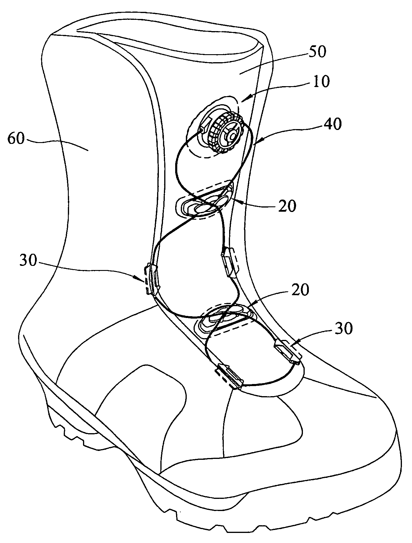
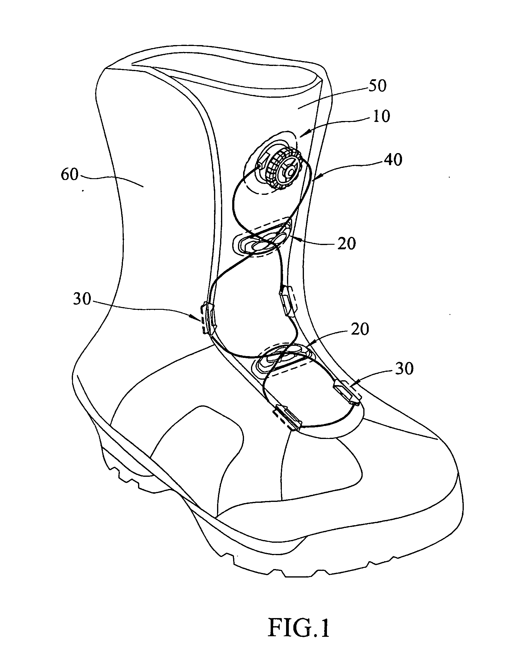
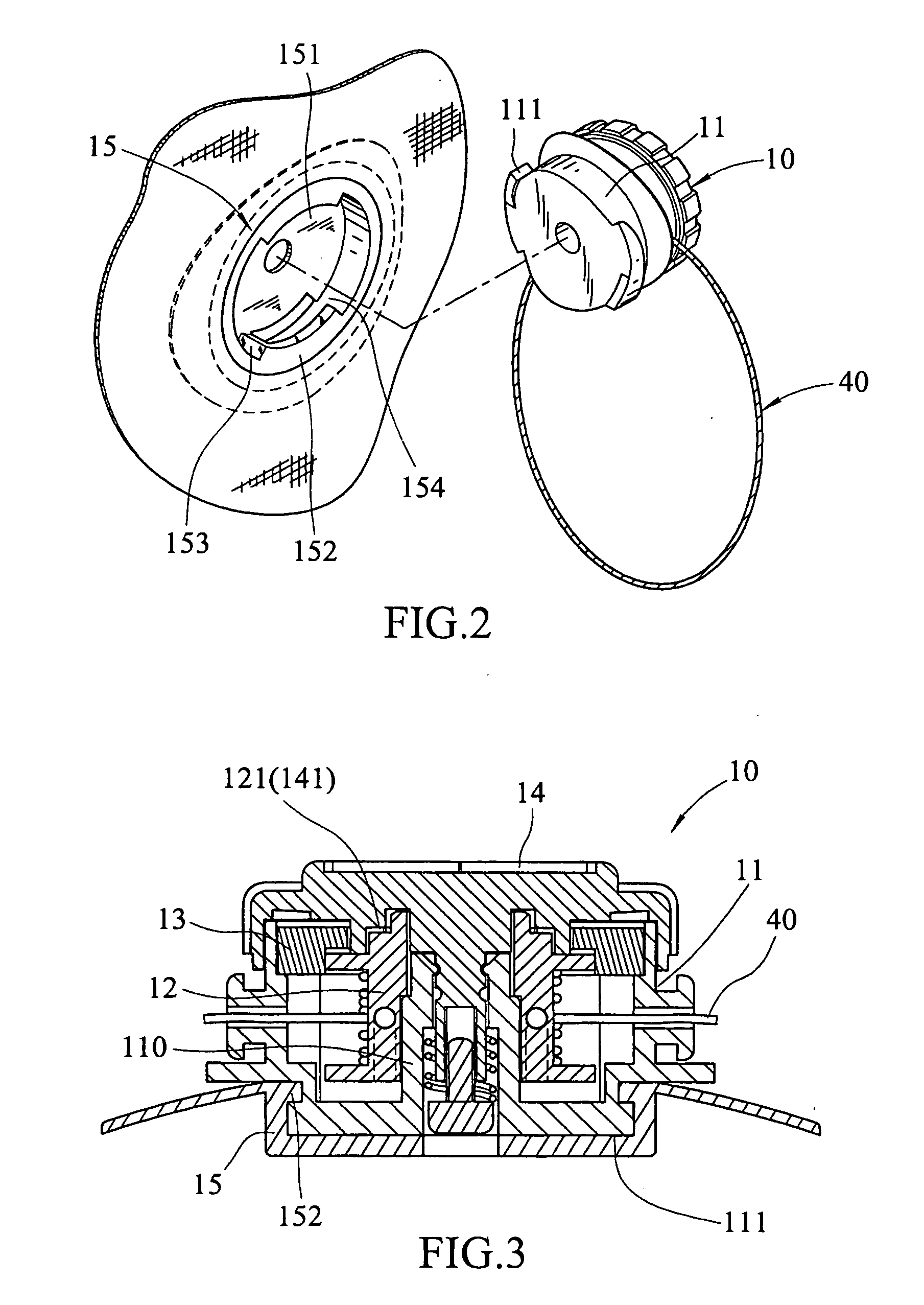
[0022]Referring to FIGS. 1 to 5, the shoelace fastening assembly of the present invention comprises a fastening device 10 fixed on a tongue 50 of a shoe and the fastening device 10 includes a base 15 fixed on the tongue 50 of the shoe, and a main part 11 which is connected to the base 15. A recess 151 is defined in the base 15 and two flanges 152 extend from an inner periphery of the recess 151 and are located diametrically opposite to each other so as to form two reception grooves 154 between the flanges 152 and an inner surface of the recess 151. The main part 11 has a tubular member 12 rotatably mounted on a mandrel 110 of the main part 11. The main part 11 has two guiding blocks 111 which are slidably engaged with the reception grooves 154 and each guiding block 111 has a thin first end and a thick second end, a smooth and spiral surface is connected between the thin first end and the thick second end. By the specific shape of the two guiding blocks 111, the main part 11 can be ...


PUM


Abstract

A shoelace fastening assembly includes a fastening device fixed on the tongue of a shoe and includes a main part which has a tubular member and a shoelace is wrapped on the tubular member. A knob is rotatably engaged with the main part and drives the tubular member to rotate in one direction. At least one intermediate member is fixed on the tongue and has a cruciform slot so that the shoelace is movably engaged with the cruciform slot. At least two hook members are respectively fixed on two flaps of the shoe and each hook member has an engaging groove with which the shoelace is movably engaged. The shoelace can be easily connected with the intermediate member and the hook members.

Description

FIELD OF THE INVENTION[0001]The present invention relates to a fastening assembly for shoelace which is easily to be connected with the parts of the fastening assembly.BACKGROUND OF THE INVENTION[0002]A conventional shoelace fastening assembly is shown in FIGS. 11 to 14 and generally includes fastening device 80 connected on the tongue 72 of the shoe 70 and the fastening device 80 includes a base 81 on which a knob 811 is rotatably mounted so as to pull or loose the shoelace 82 that is wrapped to the fastening device 80. A plurality of hook members 83 are fixed on two flaps 71 of the shoe 70 and each have a slot 831. Two holes 832 are defined through a side of the hook member 83 and communicate with the slot 831. A cover 834 is engaged with the slot 831 such that the shoelace 82 extends through the holes 832 and is limited a gap between the cover 834 and a curved inside 833 of the slot 831. A plurality of intermediate members 84 are fixed on the tongue 72 and located between the two...

Claims


Application Information

Patent Timeline
Patent Type & Authority Applications(United States)
IPC IPC(8): A43C11/00
CPCA43C1/00A43C3/00A43C11/16A43C11/165Y10T24/3737Y10T24/3703Y10T24/3724Y10T24/375Y10T24/2183
Inventor CHEN, CHIN-CHU
Owner CHEN CHIN CHU
Why Eureka
Try Eureka