
Measuring, scoring and cutting tool

a technology for measuring, scoring and cutting tools, applied in the field of utility-type knives, can solve the problems of users back to the well-known single-use tools, the complexity of the combined utility tools is not always convenient to use, and the risk of parts being lost, so as to achieve the effect of reducing the complexity and risk of parts loss, safe and durable, and reducing the risk of loss

Inactive Publication Date: 2008-07-24
ACCURATE CONCEPTS
View PDF73 Cites 7 Cited by
  • Summary
  • Abstract
  • Description
  • Claims
  • Application Information

AI Technical Summary

Benefits of technology

[0004]This invention provides an improved tool for measuring, scoring and cutting construction materials such as drywall and the like. The improved hand tool of this invention combines measuring and cutting utilities, and includes a releasable central blade securement structure allowing ready cutting blade repositioning and access to blade storage (especially convenient in a fixed blade position tool of this type). Cutting (and scoring) blade access and repositioning operations are accomplished with a minimum of complexity and risk of lost parts. The tool is compact, is convenient to use and store, is safe and durable, and is relatively inexpensive to manufacture.
[0010]It is still another object of this invention to provide and improved measuring and cutting tool that includes a releasable central blade securement structure (for both cutting and tape measure blades) that accommodates ease of cutting blade repositioning and of access to blade storage.
[0012]It is another object of this invention to provide a tool for measuring and cutting that has a minimum of parts and is thus inexpensive to manufacture.

Problems solved by technology

Such heretofore known combined utility tools have not always proven convenient to use in all circumstances, however, some tools being considered too large for all applications.
Such failure has typically led users back to the well known single use tools, even though inconvenient.
Such tools, while allowing for easy access to cutting blades, have often proven unwieldy or unduly complex to operate, some risking loss of parts during use, and have typically been expensive to manufacture (incorporating a high number of parts).
Moreover, such heretofore known tools have not always been completely safe to use, and often lack the durability necessary for repeated and rugged use in the field.

Method used


Image

  • Measuring, scoring and cutting tool
  • Measuring, scoring and cutting tool
  • Measuring, scoring and cutting tool

Examples


Embodiment Construction

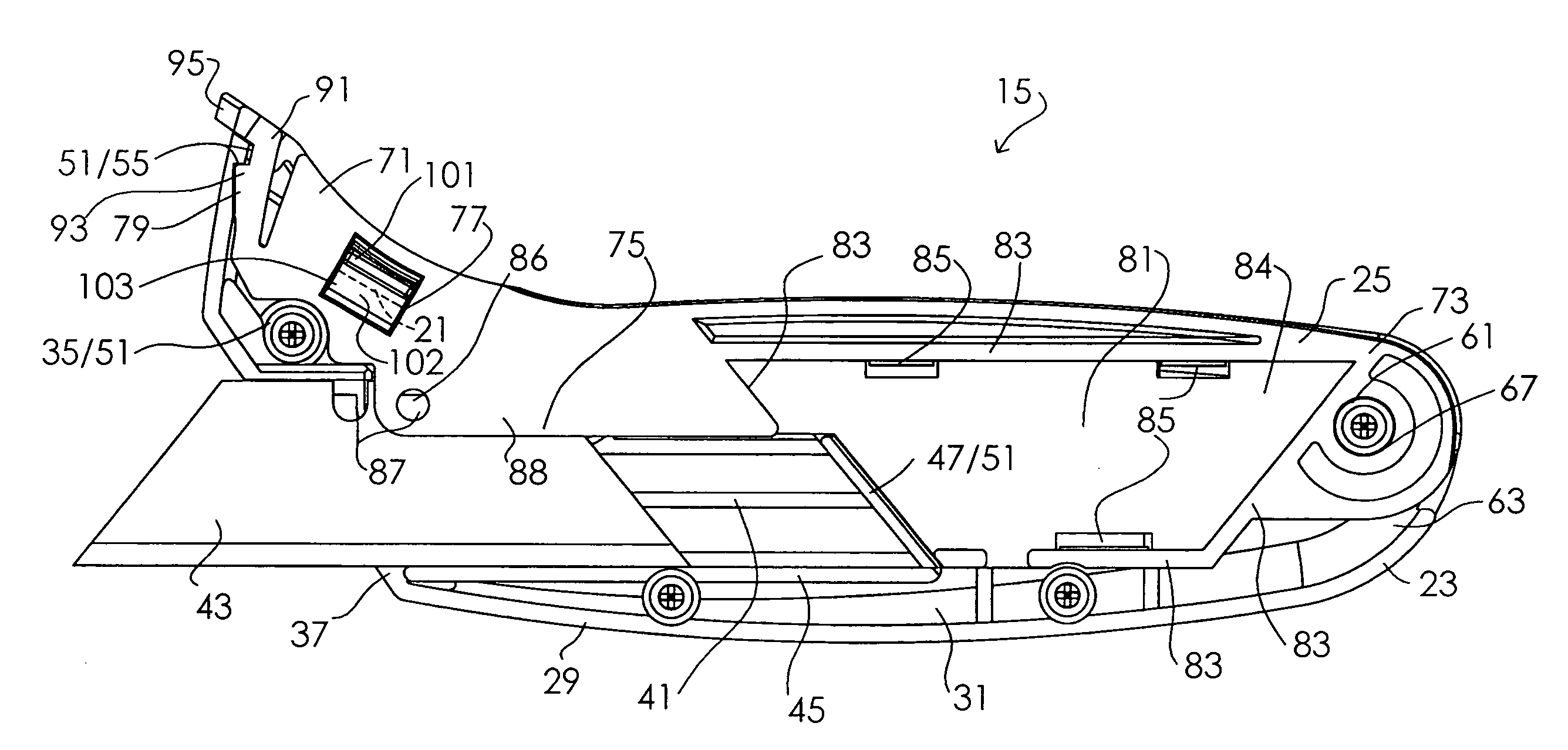
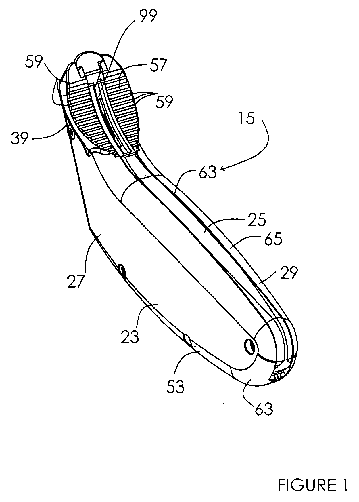
[0027]Measuring and cutting tool 15 of this invention is shown in FIGS. 1 through 7. This hand tool is primarily designed to accommodate measuring, scoring and cutting of construction materials such as drywall or the like, and is particularly configured for use with a standard tape measure 17 having a tape measure blade 19 at one end, such tape measure blades typically having a blade anchoring gap 21 therethrough (see FIG. 6).

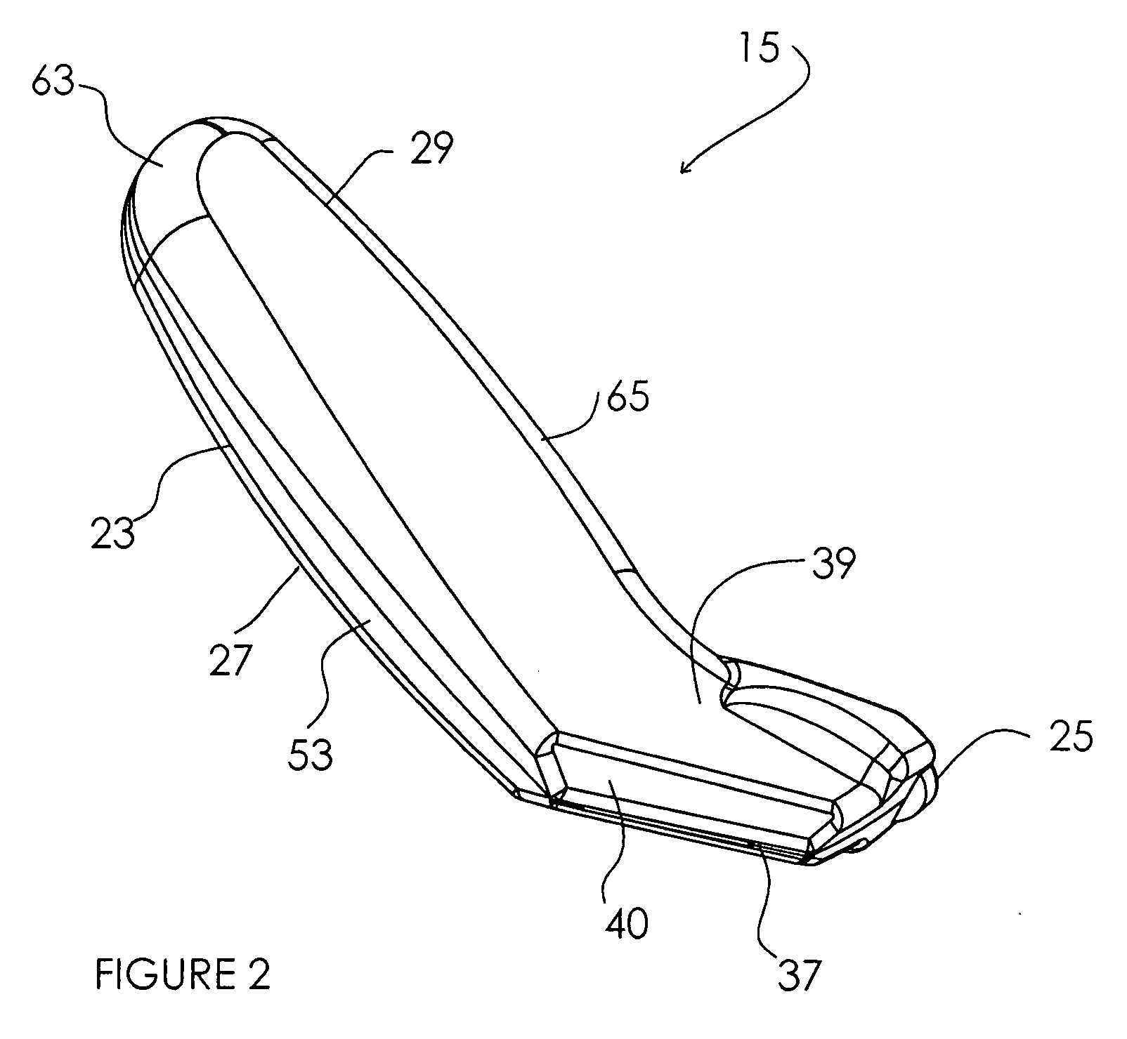
[0028]Tool 15 includes housing 23 and releasable securement 25. Housing 23 is defined by first and second housing portions 27 and 29, respectively, each having an inner opposed wall 31. Housing portion 27 and 29 are secured by screws or rivets 33 (or any other means) utilizing known structures (for example, mounting posts 35—see FIGS. 4 and 5). Cutting blade opening 37 is located through housing 23 at housing end 39 (see FIG. 2), and is defined between opposed walls 31 of each housing portion 27 and 29. The housing portions may be contoured as desired, though t...


PUM


Abstract

A hand tool for measuring, scoring and cutting construction materials is disclosed. The tool includes a housing having first and second opposed walls, with a cutting blade opening and a catch at one end thereof. A pivot is located at an opposite end of the housing. A securement having a nose and a tail is pivotably held at the housing between the walls and is deployable therefrom, the tail connected at the pivot. The nose of the securement includes a cutting blade positioning portion, a tape measure blade receiving slot and a latching structure that is releasably engageable with the catch of the housing when the securement is pivoted to an operative position. Structure defining the tape measure blade receiving slot preferably includes a lip releasably engagable at the anchoring gap feature found in the blades of most typical tape measures.

Description

FIELD OF THE INVENTION[0001]This invention relates to utility-type knives and, more particularly, relates to tools for measuring, scoring and cutting construction materials such as drywall or the like.BACKGROUND OF THE INVENTION[0002]Various hand tools utilized for cutting construction materials such as drywall or the like have been widely utilized and include such standard single use tools as keyhole saws and utility knives. Moreover, hand tools that combine measuring and cutting utility in a single tool (among other utilities) are also known and utilized (see U.S. Patent Publication No. US-2005-0022390-A1, and U.S. Pat. Nos. 6,367,154, 5,289,637, 4,993,093 and 4,255,856). Such heretofore known combined utility tools have not always proven convenient to use in all circumstances, however, some tools being considered too large for all applications. Such failure has typically led users back to the well known single use tools, even though inconvenient. Further improvements in such mult...

Claims


Application Information

Patent Timeline
IPC IPC(8): B26B11/00
CPCB25F1/00B26B11/00B26B5/001
Inventor WHITEMILLER, ANTHONY F.MURRAY, BRENT W.ANGSTEAD, RONALD A.PERCY, CLINTON L.
Owner ACCURATE CONCEPTS
Learn More