Tire pressure monitoring sensor and mounting method

a technology for monitoring sensors and tires, applied in the direction of tire measurement, vehicle components, transportation and packaging, etc., can solve the problems of sensor lifting or moving outwardly from the rim, loss of retention to the wheel, leakage of air, etc., and achieve the effect of preventing undesired movement during operation

Active Publication Date: 2008-07-24
CONTINENTAL AUTOMOTIVE SYST INC
View PDF12 Cites 32 Cited by
  • Summary
  • Abstract
  • Description
  • Claims
  • Application Information

AI Technical Summary

Benefits of technology

[0007]Yet another example spring insert is inserted within the bore of rubber housing and expanded radially upon engagement with a mandrel or the valve body. The spring insert includes a leading edge that engages the mandrel or valve stem. Engagement of the valve stem with the spring insert causes a portion of the spring insert to be driven radially outward. The radial outward movement of the spring insert causes a corresponding radial expansion of the rubber housing that generates a bias in a direction radially outward against the interior walls of the opening to provide a mechanical bias that strengthens the position of the tire pressure monitoring valve within the wheel rim.
[0008]Accordingly, the example tire pressure monitoring assemblies provide increased support for the valve stems to substantially prevent undesired movement during operation.

Problems solved by technology

During operation and high speed rotation of the wheel, the additional weight and mass of the sensor can cause the sensor to lift or move outwardly from the rim.
The stress and force generated causes movement of the valve stem that in turn can result in leakage of air or loss of retention to the wheel.

Method used


Image

  • Tire pressure monitoring sensor and mounting method
  • Tire pressure monitoring sensor and mounting method
  • Tire pressure monitoring sensor and mounting method

Examples


Embodiment Construction

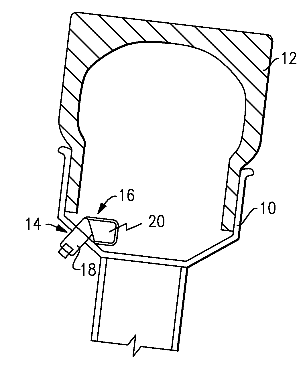
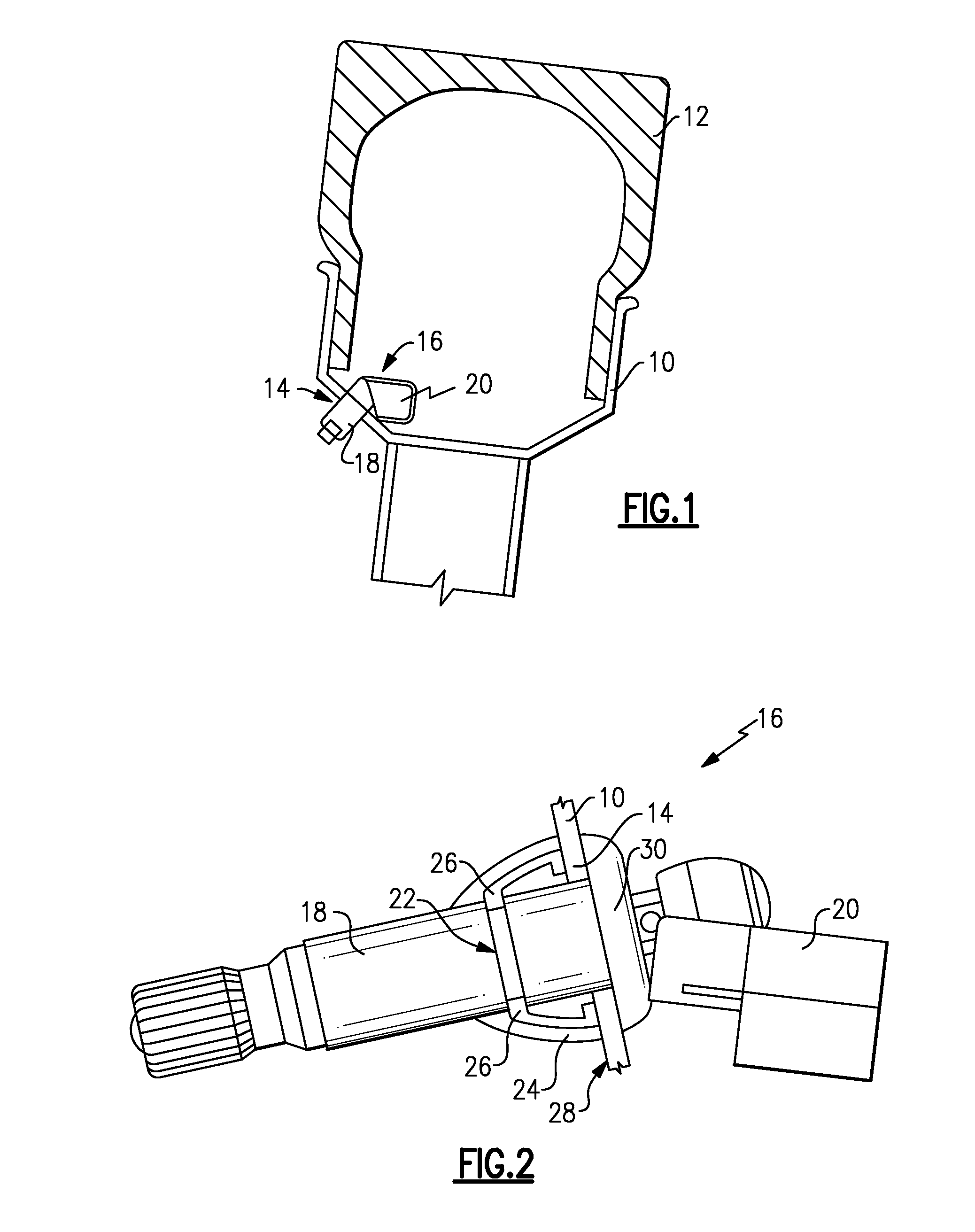
[0022]Referring to FIG. 1, a tire 12 is mounted to a wheel rim 10 and includes a tire pressure monitoring assembly 16. The tire pressure monitoring assembly 16 includes a valve stem 18 that extends through an opening 14 in the wheel rim 10 and a tire pressure sensor 20 that is attached to the valve stem 18. The sensor 20 is supported by the valve stem 18 that is in turn received and secured to the wheel rim 10 within the opening 14. The sensor 20 includes devices for monitoring and communicating conditions within the tire 12, such as pressure and temperature.

[0023]Referring to FIG. 2, the example tire pressure sensor assembly 16 includes a spring clip 26 that provides a biasing force against an outer surface 28 of the wheel rim 10. The valve stem 18 is disposed at least partially within a rubber housing 24. The rubber housing 24 is mounted to the opening 14 in the wheel rim 10 and remains in place due to the biasing force exerted by the spring clip 26. The rubber housing 24 also ext...


PUM


Abstract

A tire pressure monitoring sensor includes resilient spring members to support and resist movement during rotation of the wheel.

Description

CROSS REFERENCE TO RELATED APPLICATIONS[0001]The application claims priority to U.S. Provisional Application Nos. 60 / 897,137 and 60 / 897,136 which were both filed on Jan. 24, 2007.BACKGROUND OF THE INVENTION[0002]This invention generally relates to a tire pressure monitoring sensor and method of installing and retaining a tire pressure monitoring sensor. More particularly, this invention relates to a tire pressure monitoring including features for improved installation, retention and mounting to a wheel.[0003]A tire pressure sensor is typically mounted to a valve stem extending through the tire wheel rim. Commonly a rubber coated snap-in valve stem is pulled through an opening in the wheel rim and the resiliency of the rubber holds the valve and sensor in place. In some configurations the sensor is attached to the valve stem with a threaded member. During operation and high speed rotation of the wheel, the additional weight and mass of the sensor can cause the sensor to lift or move ...

Claims


Application Information

Patent Timeline
Patent Type & Authority Applications(United States)
IPC IPC(8): B60C23/02B60C23/04
CPCB60C23/0408B60C29/02B60C23/0494
Inventor HETTLE, MICHAELDENIAU, JEAN-CHRISTOPHE
Owner CONTINENTAL AUTOMOTIVE SYST INC
Why Eureka
Try Eureka