Electrical switching apparatus and retention system therefor

a technology of electric switching apparatus and retention system, which is applied in the direction of electrical apparatus, protective switch operating/release mechanism, contacts, etc., can solve the problems of failure of test and failure of pull test, and achieve the effect of preventing undeirable movement of individual wires

Active Publication Date: 2016-09-15
EATON INTELLIGENT POWER LIMITED
View PDF0 Cites 10 Cited by
  • Summary
  • Abstract
  • Description
  • Claims
  • Application Information

AI Technical Summary

Benefits of technology

[0008]These needs and others are met by embodiments of the disclosed concept, which are directed to an electrical switching apparatus and retention system therefor, in which a restriction mechanism prevents undesired movement of individual wires.

Problems solved by technology

A significant drawback caused by employing the different wires is that the pull test is not always satisfied.
More specifically, pull testing the different wires results in undesirable displacement of the individual wires, thereby failing the test and the ability to get the appropriate certification.

Method used


Image

  • Electrical switching apparatus and retention system therefor
  • Electrical switching apparatus and retention system therefor
  • Electrical switching apparatus and retention system therefor

Examples


Embodiment Construction

[0018]As employed herein, the term “number” shall mean one or an integer greater than one (i.e., a plurality).

[0019]As employed herein, the statement that two or more parts are “connected” or “coupled” together shall mean that the parts are joined together either directly or joined through one or more intermediate parts.

[0020]As employed herein, the statement that two or more parts or components “engage” one another shall mean that the parts touch and / or exert a force against one another either directly or through one or more intermediate parts or components.

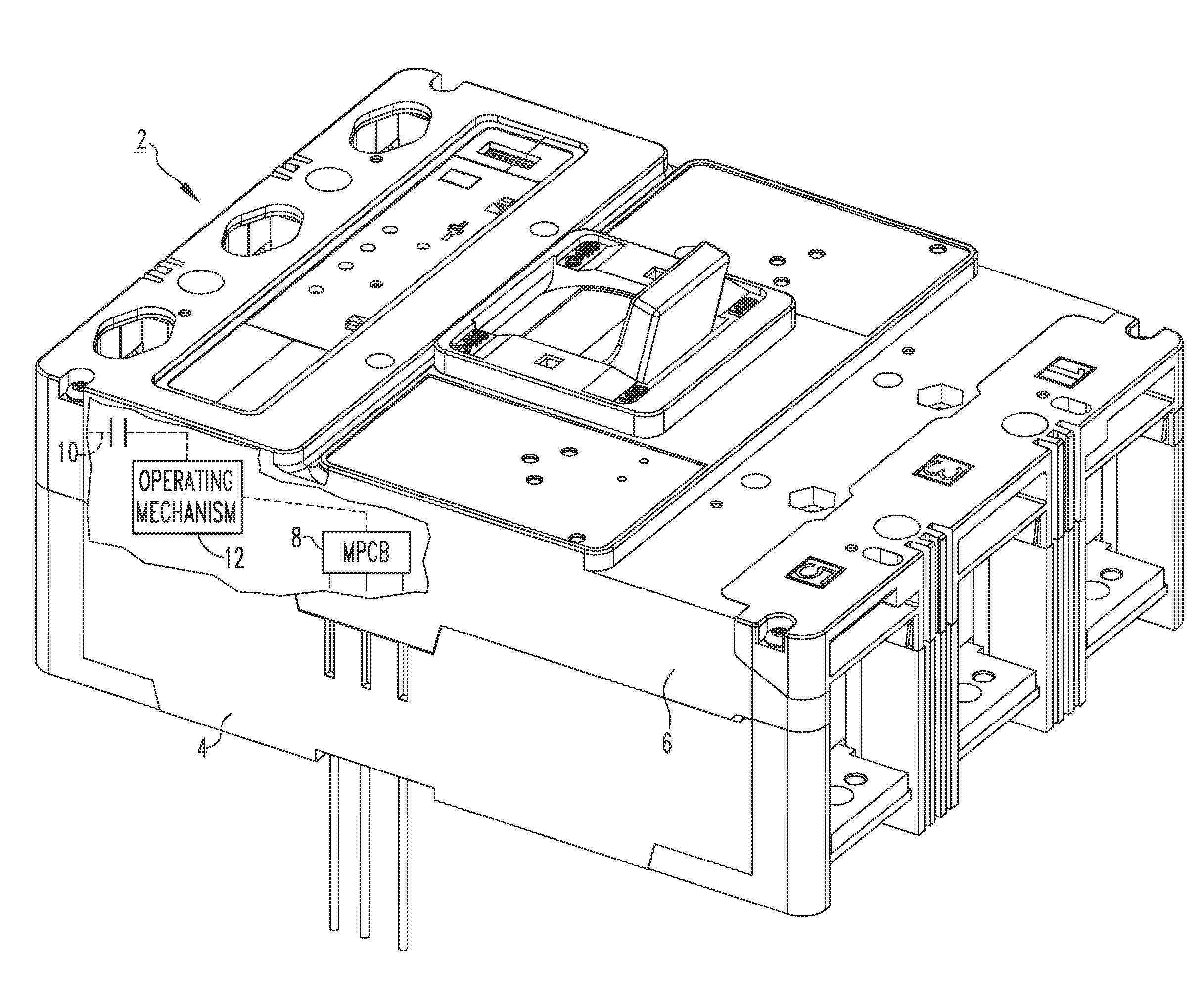
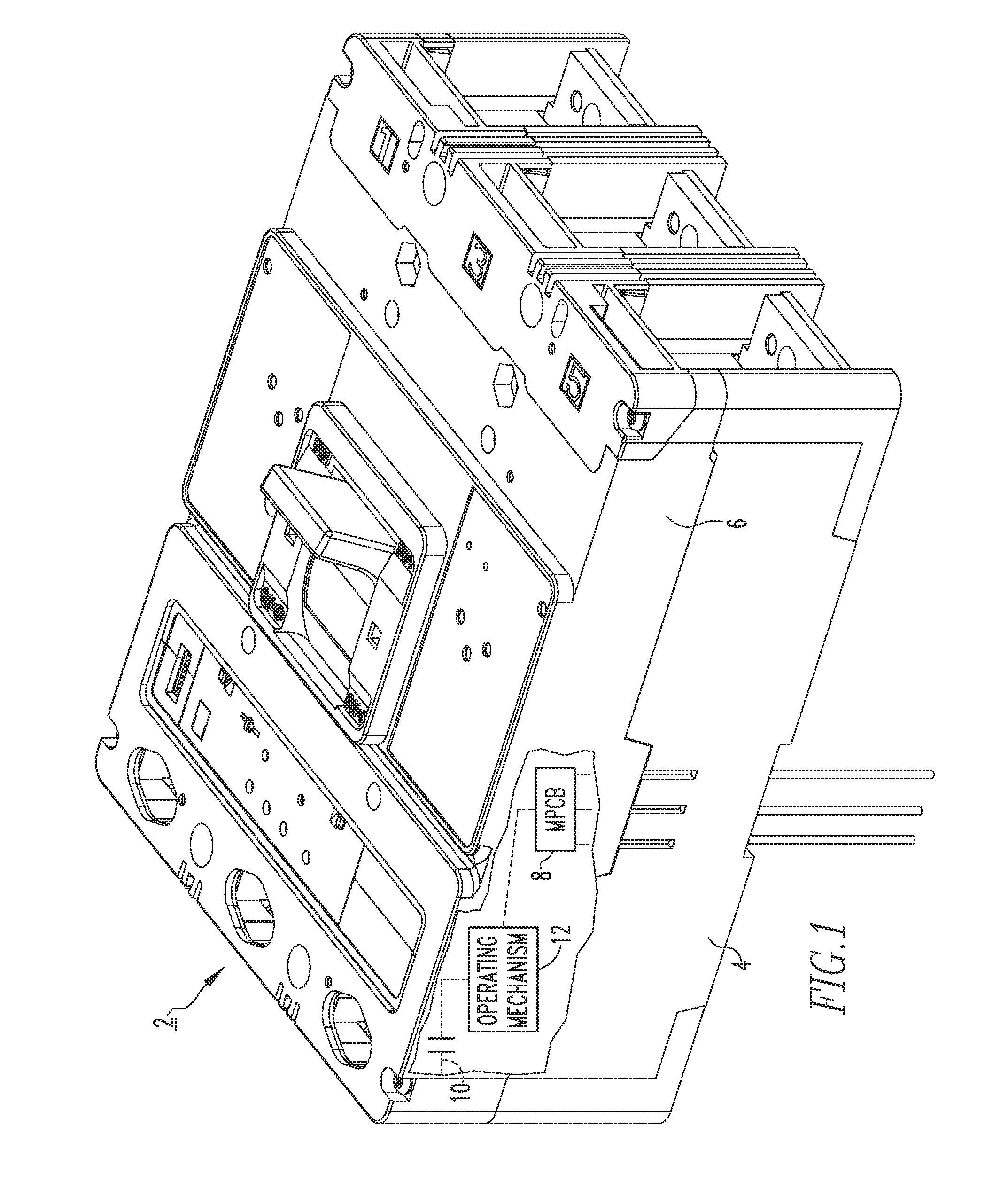
[0021]FIG. 1 shows an electrical switching apparatus (e.g., molded case circuit breaker 2) in accordance with a non-limiting embodiment of the disclosed concept. The example circuit breaker 2 includes a frame 4 and a cover 6 coupled to the frame 4. The circuit breaker 2 further includes an electrical component (e.g., without limitation, main printed circuit board 8, shown in simplified form) enclosed by the frame 4 and the cover...


PUM


Abstract

A retention system is for an electrical switching apparatus. The electrical switching apparatus includes a frame having a number of slots, a cover coupled to the frame, an electrical component enclosed by the frame and the cover, separable contacts enclosed by the frame and the cover, and an operating mechanism to open and close the separable contacts. The retention system includes: at least one bundle of wires having a plurality of individual wires extending through a corresponding one of the number of slots to be electrically connected to the electrical component; and at least one restriction mechanism each comprising an insulative sleeve surrounding a corresponding one of the at least one bundle of wires, and a blocking member connected to the insulative sleeve. The blocking member engages the frame to prevent undesired movement of the individual wires with respect to the corresponding one of the number of slots.

Description

BACKGROUND[0001]1. Field[0002]The disclosed concept pertains generally to electrical switching apparatus, such as for example, circuit breakers. The disclosed concept also pertains to retention systems for electrical switching apparatus.[0003]2. Background Information[0004]Electrical switching apparatus are used to protect electrical circuitry from damage due to a trip condition, such as, for example, an overcurrent condition, an overload condition, an undervoltage condition, a relatively high level short circuit or fault condition, a ground fault or arc fault condition. Molded case circuit breakers, for example, include at least one pair of separable contacts which are operated either manually by way of a handle located on the outside of the case, or automatically by way of a trip unit in response to the trip condition.[0005]Some molded case circuit breakers have wires that attach to internal components and exit the circuit breaker for use with external systems. In order for the ci...

Claims


Application Information

Patent Timeline
Patent Type & Authority Applications(United States)
IPC IPC(8): H01R4/28H01H71/10
CPCH01H71/10H01R4/28H01H1/5822H01H1/5844H01H1/5855
Inventor JUREK, RAYMOND LEEPUHALLA, CRAIG JOSEPHKUZNIARSKI, THOMAS TED
Owner EATON INTELLIGENT POWER LIMITED
Why Eureka
Try Eureka