MEMS device

a micro-mirror device and oscillating angle technology, applied in piezoelectric/electrostrictive/magnetostrictive devices, micro-electromechanical systems, instruments, etc., can solve the problems of increasing the power consumption of the mems micro-mirror device, bending the arms, and reducing the cross-sectional area, so as to reduce the cross-sectional area, reduce the risk of breaking, and increase the stiffness at the meander

Active Publication Date: 2015-06-18
GOOGLE LLC
View PDF1 Cites 12 Cited by
  • Summary
  • Abstract
  • Description
  • Claims
  • Application Information

AI Technical Summary

Benefits of technology

[0024]The first and second torsional arms may be configured to be stiffer at the meanders than at portions of the arms which are between successive meanders. The increased stiffness at the meanders is achieved since the arms larger or thicker at each meander.
[0025]The cross sectional area of the first and second torsional arms may be larger at each of the meanders compared to at portions of the arms which are between successive meanders. This configuration enables a more homogenous distribution of stress throughout the first and second torsional arms, thus making the first and second torsional arms less susceptible to breakage. Also the reduced cross-sectional area of the portions between the successive meanders will reduce the average stiffness of the first and second torsional arms, enabling the mirror to be more easily oscillated and thus reducing the power consumption of the MEMS device. Also, this configuration ensures that the first and second torsional arms are stiffer at the meanders than at portions of the arms which are between successive meanders.

Problems solved by technology

However the size of the oscillating angle and size of the reflective surfaces is limited by the fragility of the straight torsional arms which connect the micro-mirror to the fixed part of the MEMS micro-mirror device.
Large oscillations of the micro-mirror generate stresses in the straight torsional arms which can cause the straight torsional arms to break.
To avoid breakage of the straight torsional arms the arms are usually made stiffer; however making the arms stiffer increases the power consumption of the MEMS micro-mirror device since more power is required to oscillate the micro-mirror.
The fragility of the straight torsional arms also decreases the shock-resistance of the MEMS micro-mirror device.
A decrease in shock-resistance will mean that the MEMS micro-mirror device is more susceptible to breakage if dropped.
This torque stress can cause bending of the straight torsional arms.
Additionally, straight torsional arms are long; the length of the torsional arms increases the overall size of the MEMS micro-mirror device.

Method used


Image

  • MEMS device
  • MEMS device
  • MEMS device

Examples


Embodiment Construction

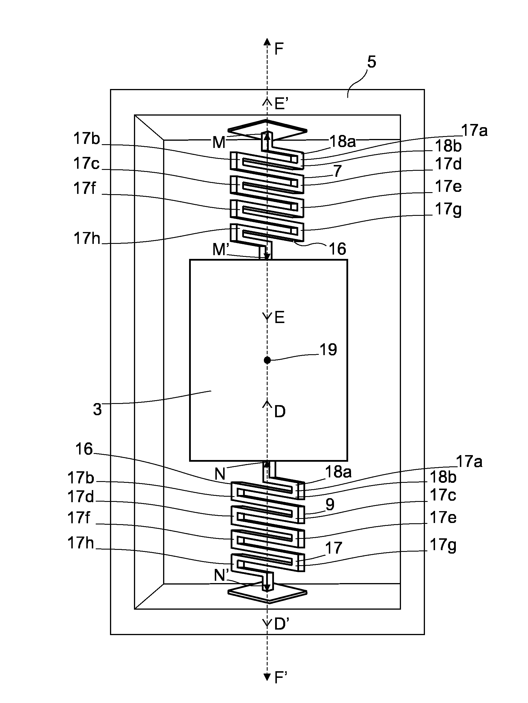
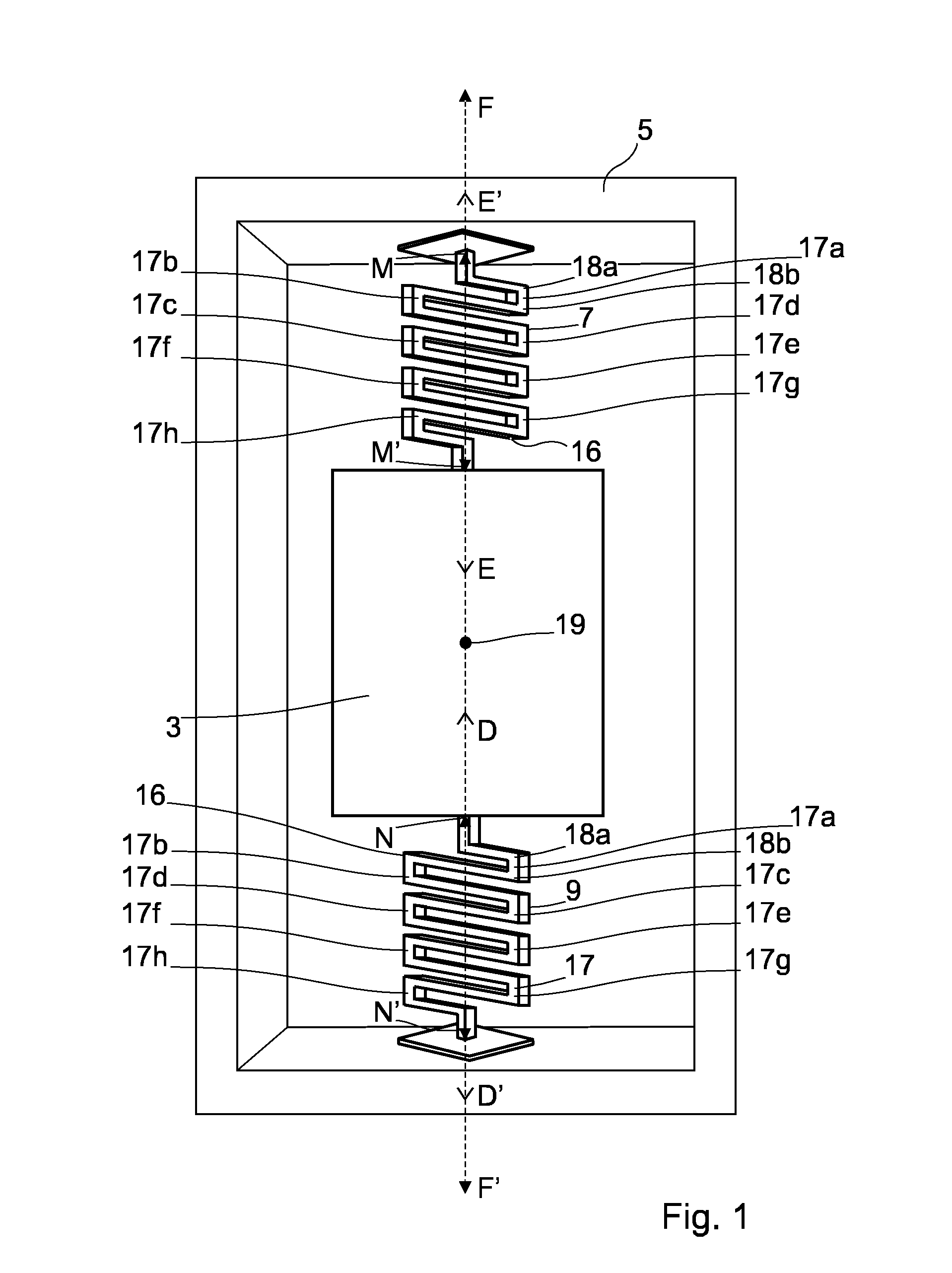
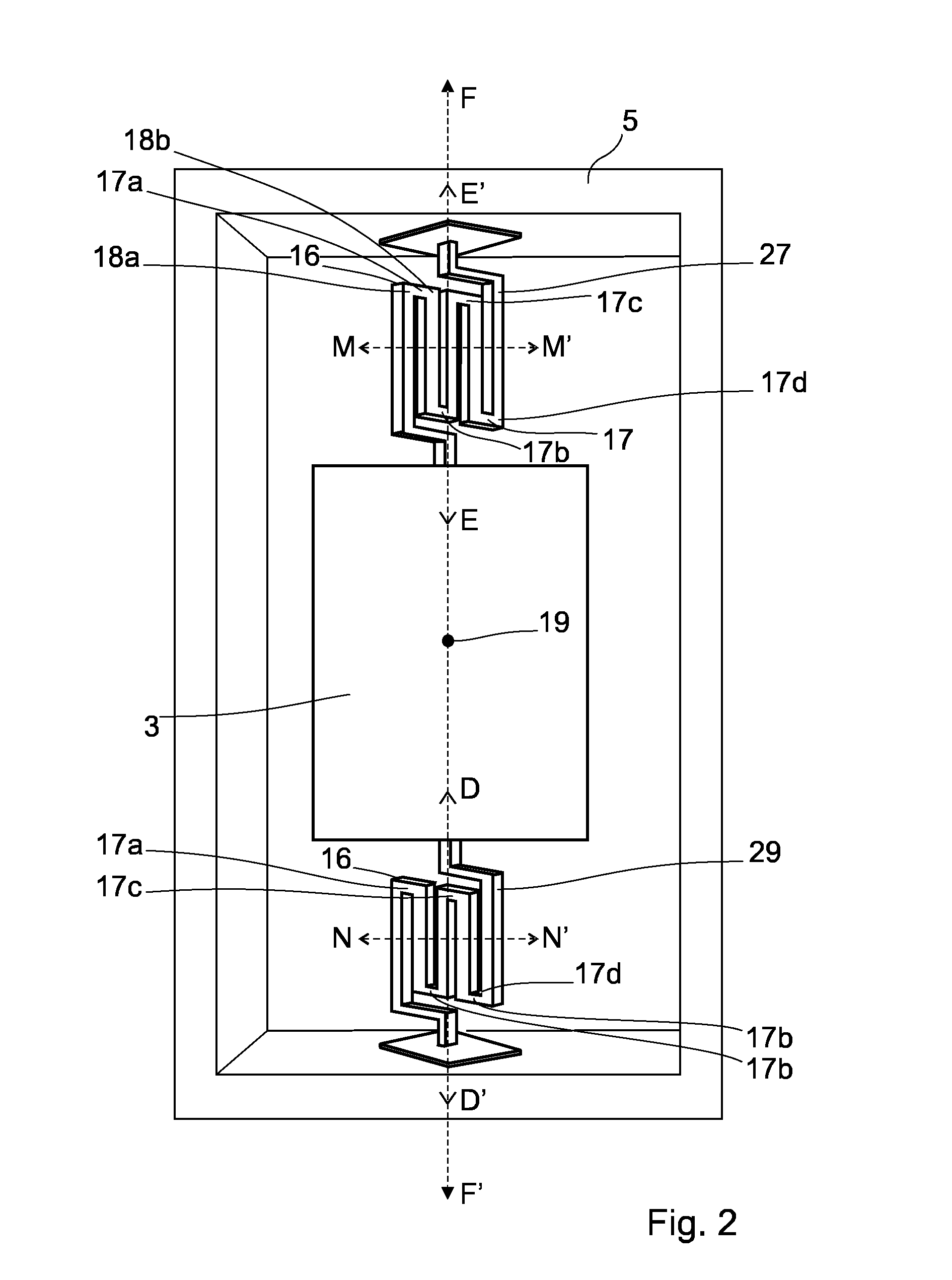
[0043]FIG. 1 is a plan view of a MEMS device 1 according to a first embodiment of the present invention.

[0044]The MEMS device 1 comprises, a mirror 3 which is connected to a fixed portion 5 by means of a first and second torsional arm 7,9. Each of the first and second torsional arms 7,9 are configured such that they can twist about torsional axes E-E′, D-D′ respectively, so as to oscillate the mirror 3 about a first oscillation axis F-F′. The first and second torsional arms 7,9 are arranged symmetrically relative to the first oscillation axis F-F′.

[0045]In this particular example the torsional arms 7,9 are arranged such that both the torsional axes E-E′, D-D′ are parallel and are in alignment with one another; however, it will be understood that the torsional arms 7,9 may have an alternative arrangement so that the torsional axes E-E′, D-D′ are off-set from one another and / or may not be parallel. Also, in this particular example the torsional arms 7,9 are arranged so that the torsio...


PUM


Abstract

According to the present invention there is provided a MEMS device comprising, a mirror which is connected to a fixed portion by means of a first and second torsional arm, each of the first and second torsional arms are configured such that they can twist about torsional axes so as to oscillate the mirror about a first oscillation axes, and wherein the first and second torsional arms are each configured to have two or more meanders and wherein the first and second torsional arms are arranged symmetrically relative to the first oscillation axis.

Description

FIELD OF THE INVENTION[0001]The present invention relates to a MEMS device, and in particular to a MEMS device which comprises torsional arms which are configured so that an improved distribution of stress throughout these torsional arms is achieved, thereby making the MEMS device is less susceptible to breakage and enabling the MEMS device to have improved shock-resistance.DESCRIPTION OF RELATED ART[0002]A MEMS micro-mirror device is a device that contains an optical MEMS (Micro-Electrical-Mechanical-System). The optical MEMS may comprise a cylindrical, oval rectangular, square or any shape micro-mirror that is adapted to move and to deflect light over time. The micro-mirror is connected by straight torsion arms to a fixed part and can tilt and oscillate along one or two axis. For example it can oscillate vertically and horizontally. The Different actuation principles can be used, including electrostatic, thermal, electro-magnetic or piezo-electric or a combination of those. MEMS d...

Claims


Application Information

Patent Timeline
Patent Type & Authority Applications(United States)
IPC IPC(8): G02B26/08G02B26/10B81B3/00
CPCG02B26/0833G02B26/085G02B26/101B81B3/0072B81B2201/042B81B2203/0154B81B2203/0181B81B2203/06G02B26/105
Inventor ABELE, NICOLASKHECHANA, FAOUZIGAMET, JULIEN
Owner GOOGLE LLC
Why Eureka
Try Eureka