Concrete block making machine and method

a concrete block and machine technology, applied in the direction of dough shaping, manufacturing tools, applications, etc., can solve the problems of irregular, shiny, non-split surface of the workpiece, and workpiece splits (cracks)

Inactive Publication Date: 2008-07-24
FIREDMAN DOUGLAS KELLER +1
View PDF40 Cites 42 Cited by
  • Summary
  • Abstract
  • Description
  • Claims
  • Application Information

AI Technical Summary

Problems solved by technology

This is not an undesirable characteristic in some landscaping applications, however it is a drawback in many applications where there is a demand for building blocks having a natural appearance.
As the forces on the blades are increased, the workpiece splits (cracks), generally along the plane of alignment of the blades.
However, a disadvantage associated with blocks prepared by the splitting process is that the edges of the faces resulting from the industry-standard splitting process are generally well-defined (i.e. regular and sharp), and the non-split surfaces of the blocks, which are sometimes in view in landscaping applications, are regular, shiny, and non-textured.
The edges therefore undesirably have a machine-made appearance.
As the drum is rotated, the blocks bang against each other, knocking off their sharp edges, and also chipping and scarring the edges and faces of the blocks, making them look less machine manufactured, and more weathered.
Unfortunately, there are several drawbacks to the use of tumbling processes.
First, the tumbling process is costly.
This extensive off-line processing is expensive for the concrete block manufacturer.
An additional expense arises due to the substantial spoilage of blocks that can occur as the blocks break apart in the tumbler.
Further, the tumbling equipment itself tends to be quite expensive, and is a high maintenance item.
These machines are typically expensive, and they require space on the production line, which space is often not available in block plants, particularly older plants.
Use of this machine also, often slows down production.
The process is time consuming in part because each block must typically be manipulated by flipping, rotation or other methods to attack each of its edges, and the concrete block manufacturing process can only move as fast as the hammermill can operate on each block.
Additionally, use of the hammermill-type machine creates many of the inefficiencies described herein-above with regard to tumbling.

Method used


Image

  • Concrete block making machine and method
  • Concrete block making machine and method
  • Concrete block making machine and method

Examples


Embodiment Construction

[0023]While this invention is susceptible of embodiments in many different forms, the drawings shown and the specification describe in detail several embodiments of the invention. It should be understood that the drawings and the specification are to be considered an exemplification of the principles of the invention. They are not intended to limit the broad aspects of the inventive method and related equipment to the embodiments illustrated.

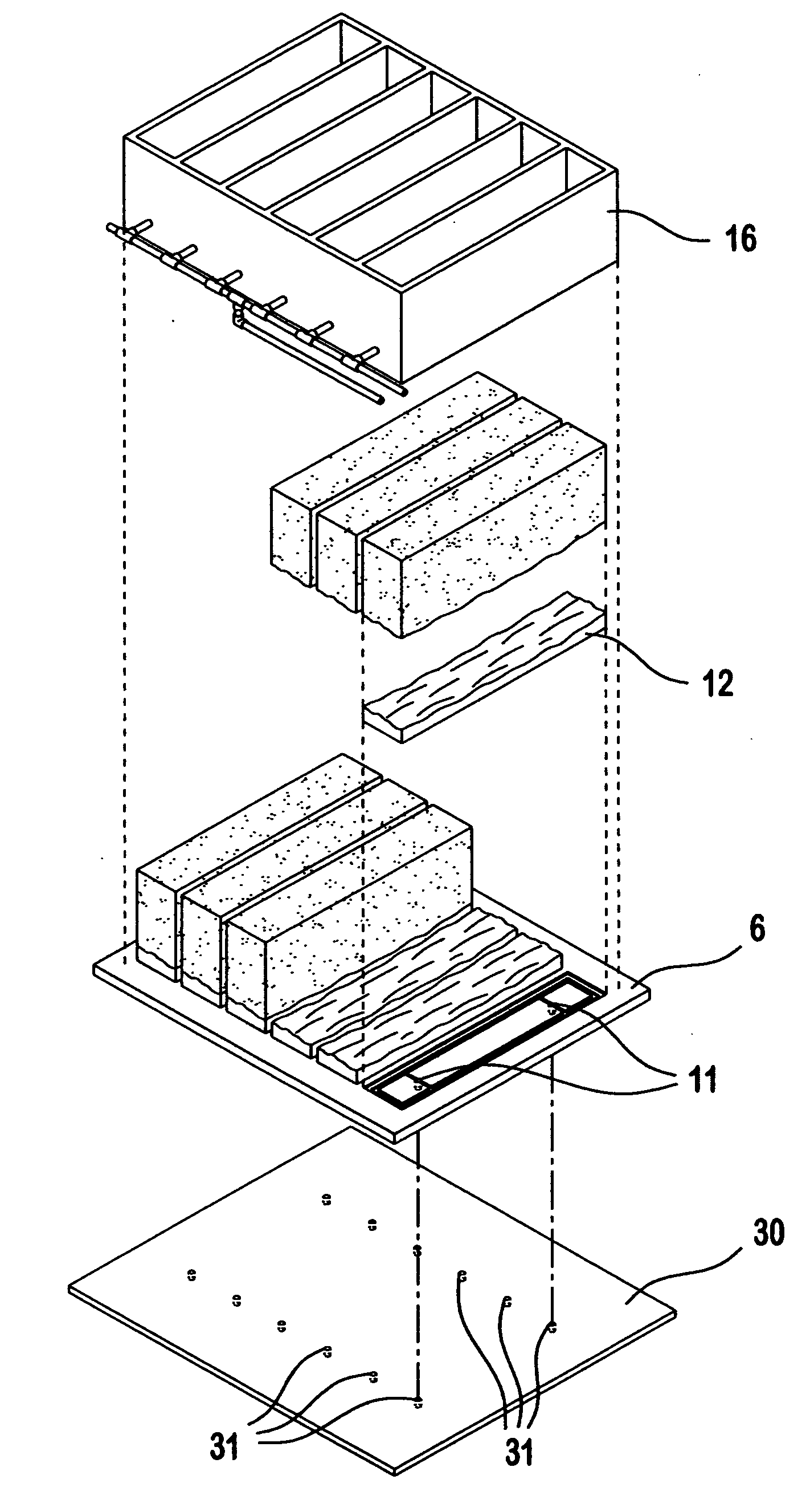
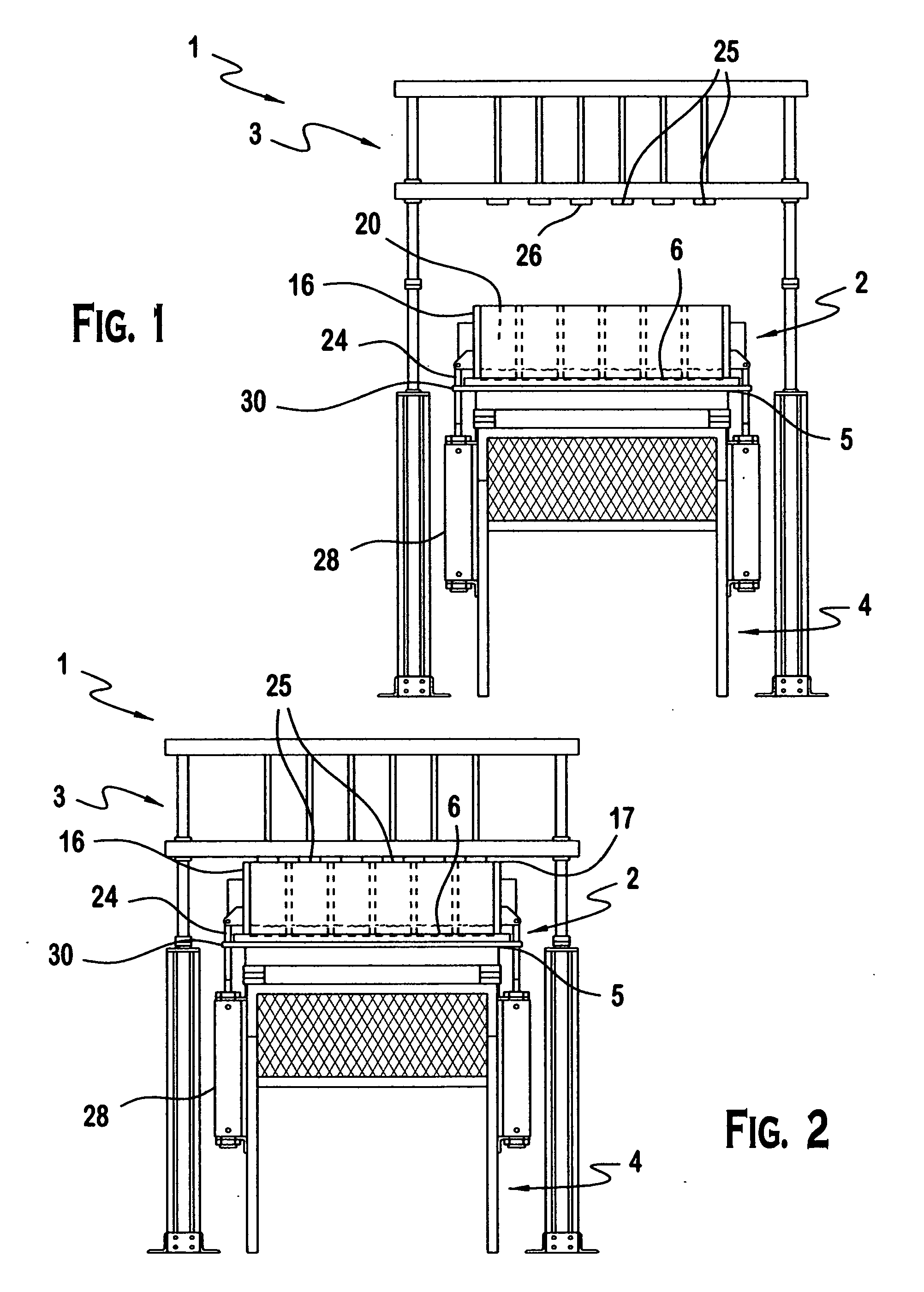
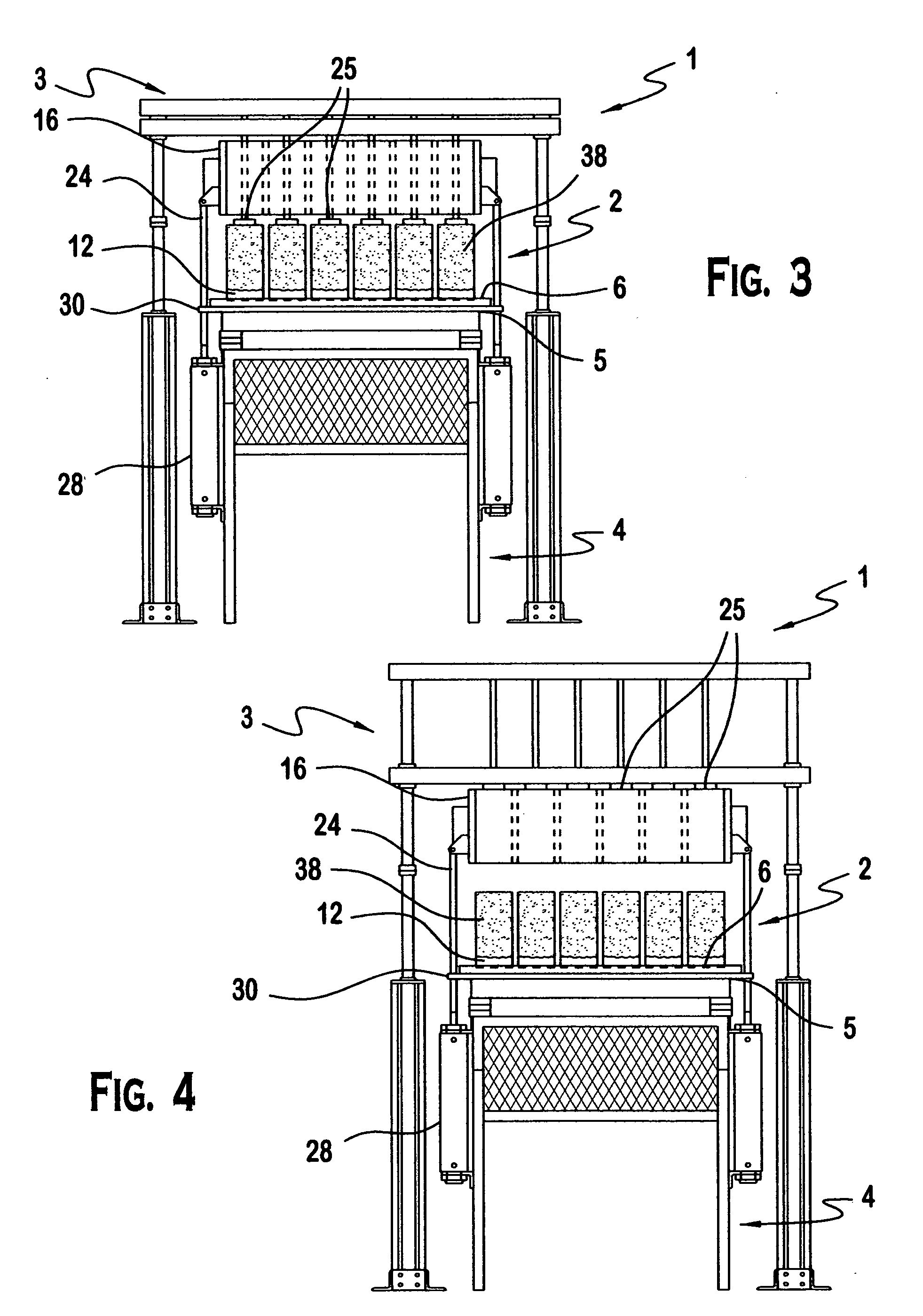
[0024]The present invention provides a method for making decorative concrete blocks, and related equipment for performing the method. Applicants' invention provides a method and related equipment that do not suffer from at least one of the disadvantages of conventional decorative concrete block making methods and equipment. Applicants' method has at least one of the following attributes: creates a more natural rock face appearance to the faces of decorative concrete wall blocks, by among other things, eliminating the regular, sharp face edges th...


PUM

PropertyMeasurementUnit
pressureaaaaaaaaaa
diameteraaaaaaaaaa
pressureaaaaaaaaaa

Abstract

A method for manufacturing decorative concrete blocks for decorative garden walls is presented, along with a machine suitable for practicing the method.

Description

BACKGROUND[0001]The present invention relates to a method for manufacturing decorative concrete blocks, and a machine suitable for practicing the method.[0002]Concrete masonry blocks are commonly used for landscaping purposes. Such blocks are used to create, for example decorative garden walls having various sizes and designs. Concrete masonry blocks are typically made in high speed production plants, and they are usually uniform in appearance. This is not an undesirable characteristic in some landscaping applications, however it is a drawback in many applications where there is a demand for building blocks having a natural appearance.[0003]One way to make concrete masonry blocks less uniform, and more natural appearing, is to use a splitting process to create a “rock face” on the block. Typically, in this process, a large concrete workpiece which has been adequately cured is split or cracked apart to form two blocks. The resulting faces of the two blocks along the plane of the spli...

Claims


Application Information

Patent Timeline
Patent Type & Authority Applications(United States)
IPC IPC(8): B28B1/08B28B21/02
CPCB28B1/0873B28B3/06B28B7/007B28B15/005B28B7/366B28B11/245B28B7/12
Inventor FIREDMAN, DOUGLAS KELLERMCLAUGHLIN, JOSEPH FRANCIS
Owner FIREDMAN DOUGLAS KELLER
Why Eureka
Try Eureka