Active Wireless Tag And Auxiliary Device For Use With Monitoring Center For Tracking Individuals or Objects

a technology of auxiliary devices and wireless tags, which is applied in the direction of individual entry/exit registers, instruments, high-level techniques, etc., can solve the problems of limited ability of tags to properly function, limited range of hmu, and limited range of tracking systems of this type, so as to reduce battery consumption, minimize contention, and expand the range of hmu

Active Publication Date: 2008-07-24
SATELLITE TRACKING OF PEOPLE
View PDF17 Cites 57 Cited by
  • Summary
  • Abstract
  • Description
  • Claims
  • Application Information

AI Technical Summary

Benefits of technology

[0011]The tracking device can also have a third operational mode, when communication is established between the tracking device and the auxiliary device. In the third operational mode, the position determining circuitry is placed in a reduced power state. The second wireless circuitry receives the auxiliary device ID from the auxiliary device and the first wireless circuitry communicates the auxiliary device ID to the remote location. This mode can be used to create an inclusion zone. The decision to create an inclusion zone can be at least partially based on the received auxiliary device ID. The tracking device can also include a battery for powering circuitry associated with, or internal to, the tracking device. Battery consumption is reduced when the position determining circuitry is placed in a reduced power state. The tracking device can also include a housing and a strap that secures the tracking device to an object or individual and tamper detection circuitry that detects unauthorized removal or opening of the tracking device.
[0012]The tracking device can include signal strength circuitry associated with the second wireless circuitry. This signal strength circuitry can be used by the tracking device to determine whether radio energy received by the second wireless circuitry is below a predetermined threshold. This can provide range adjustment capability for the second wireless link. The tracking device can also include i) time slot allocation circuitry and / or ii) frequency allocation circuitry. This circuitry can allow the tracking device to minimize contention for frequencies or time slots associated with the second wireless circuitry.

Problems solved by technology

The tracking system of this type is limited in that it can only provide an indication of the presence or absence of the individual at the monitored location at a given time.
This type of system cannot offer location information if the individual leaves the monitored location.
The tag's ability to properly function is limited by the capabilities of the tag's battery and the ability of the tag's circuitry to function properly in different locations.
Current GPS based tracking systems, for example, will not function properly when GPS reception becomes impaired or is lost.
In addition, the demands of system applications place increasing power loads and operating time requirements on the tag's batteries.
Both of these shortcomings can be especially acute in offender tracking and monitoring applications where loss of offender locational monitoring is unacceptable.

Method used


Image

  • Active Wireless Tag And Auxiliary Device For Use With Monitoring Center For Tracking Individuals or Objects
  • Active Wireless Tag And Auxiliary Device For Use With Monitoring Center For Tracking Individuals or Objects
  • Active Wireless Tag And Auxiliary Device For Use With Monitoring Center For Tracking Individuals or Objects

Examples


Embodiment Construction

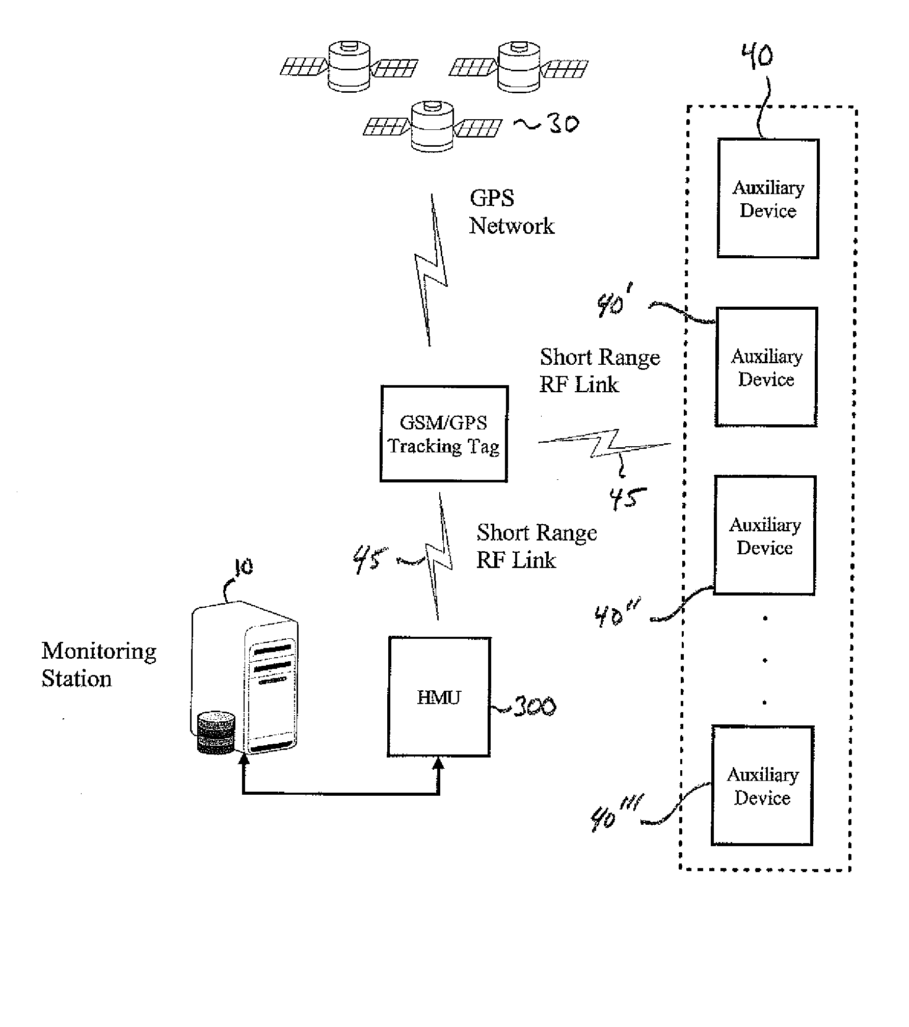
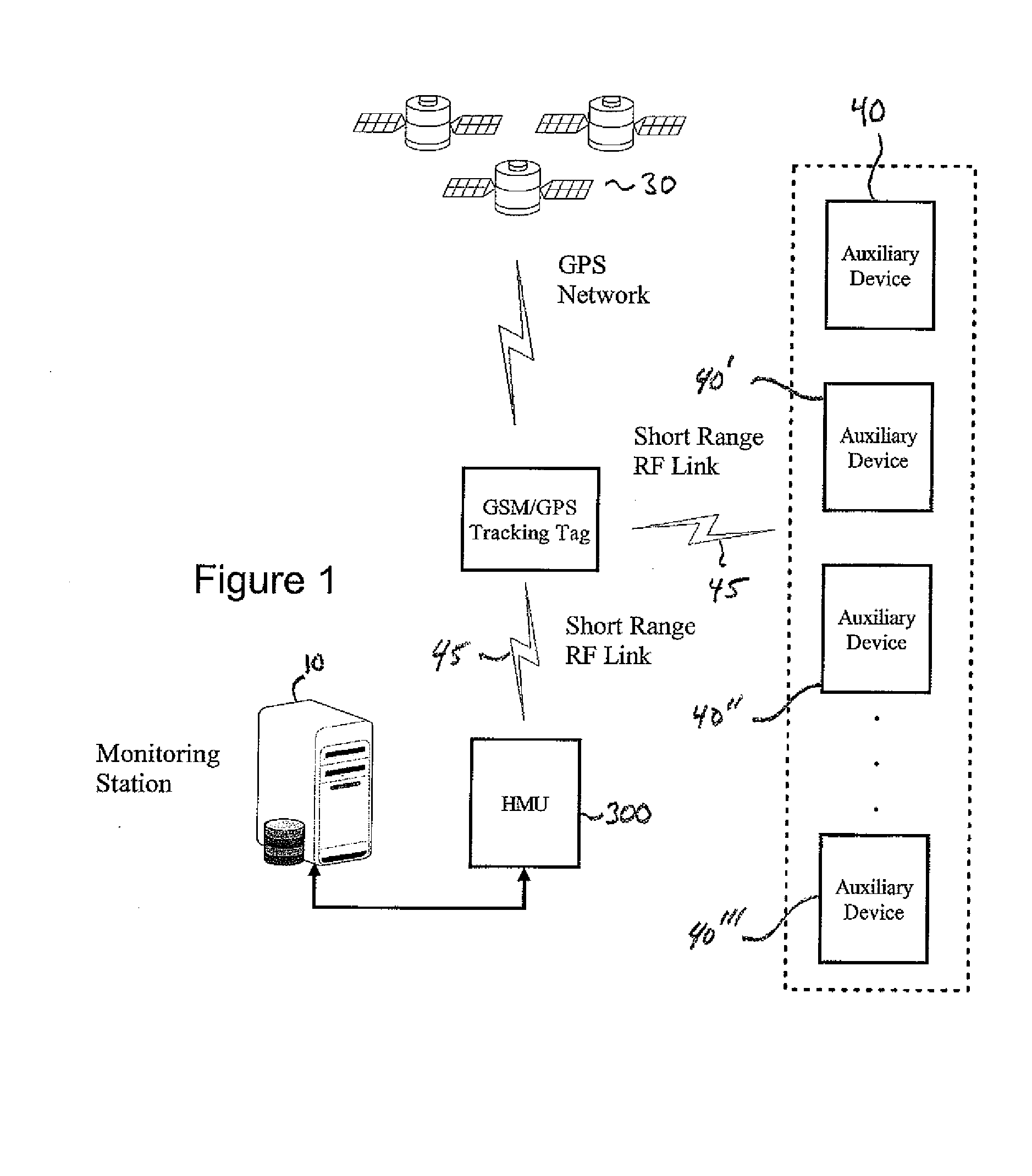
[0021]FIG. 1 shows a block diagram of a system in accordance with the invention. The system includes a central monitoring system (CMS) 10, a tracking tag 20 operable to communicate with a Global Positioning Satellite (GPS) network 30 and one or more auxiliary devices 40. The strap or tag may incorporate tamper detection using a variety of well-know technologies. The tag 20 can be attached to an object or individual using a strap or other suitable means of connection. For example, the tag can be attached to a package that is being transported from one location to another. In the alternative, the tag can be attached to in individual under “house arrest” that being monitored for compliance. Numerous other scenarios can be envisioned without departing from the scope of the invention.

[0022]The tag 20 communicates with the GPS network 30 and a wireless network 25 to respectively obtain geographic location information and to exchange data with the CMS 10. The CMS monitors the location of t...


PUM


Abstract

The invention is directed to a location tracking device and auxiliary device for use with a monitoring center for tracking individuals or objects. The location tracking device has position determining circuitry and first wireless circuitry that communicates position data representative of the location of the tracking device to a remote location (e.g., a monitoring station). The tracking device also has second wireless circuitry that communicates with the auxiliary device. The tracking device has at least two operational modes. The tracking device switches operational modes when communication is established between the tracking device and the auxiliary device. The auxiliary device generally has an associated auxiliary device ID and wireless circuitry that communicates the auxiliary device ID to the location tracking device. The tracking device has a first operational mode, when communication is not established with the auxiliary device, wherein the position determining circuitry is maintained in a normal power state. The tracking device can also have a second operational mode, when communication is established between the tracking device and the auxiliary device. In the second operational mode, the second wireless circuitry receives the auxiliary device ID from the auxiliary device and the first wireless circuitry communicates the auxiliary device ID to the remote location. The tracking device can also have a third operational mode, when communication is established between the tracking device and the auxiliary device. In the third operational mode, the position determining circuitry is placed in a reduced power state.

Description

CROSS-REFERENCE TO RELATED APPLICATIONS[0001]The present application claims priority of U.S. Provisional Patent Application Ser. No. 60 / 840,844, filed Aug. 29, 2006, and U.S. Provisional Patent Application Ser. No. 60 / 859,232, filed Nov. 15, 2006, the entire contents of which are incorporated herein by reference. This application is also related to concurrently filed U.S. patent application Ser. No. ______ entitled “Wireless Tag and Auxiliary Device for Use With Home Monitoring Unit for Tracking Individuals or Objects.”FIELD OF THE INVENTION[0002]The present invention relates to systems which provide location tracking and monitoring of a portable tracking device or “tag” that is affixed to an individual or other object, and in which the device periodically communicates data to a remote monitoring station. More specifically, the present invention relates to the implementation of limited RF capability in the tag and another system device, hereinafter “auxiliary device” to provide impr...

Claims


Application Information

Patent Timeline
Patent Type & Authority Applications(United States)
IPC IPC(8): H04Q7/00H04W4/029H04W4/02
CPCY02B60/50G07C9/00111G07C9/28Y02D30/70H04W4/02G08B5/00G08B23/00H04W4/029
Inventor FREATHY, STEPHENPRIDMORE, PAULLOGAN, STEVEN W.
Owner SATELLITE TRACKING OF PEOPLE
Why Eureka
Try Eureka