Vertebra connection member

a technology of vertebrae and connections, applied in the field of vertebrae connection members, can solve the problems of not being able to connect in a desired manner via a rod, and achieve the effects of reducing the load on the tissue surrounding the vertebrae connected by reducing the external dimensions of the vertebrae connection member, and ensuring the connection

Inactive Publication Date: 2008-07-24
SHOWA IKA KOHGYO
View PDF19 Cites 18 Cited by
  • Summary
  • Abstract
  • Description
  • Claims
  • Application Information

AI Technical Summary

Benefits of technology

[0009]The aforementioned surface roughening treatment is preferably performed by sandblasting. By employing such configuration, the surface roughening treatment can be performed in a simple manner.
[0010]Furthermore, the head section holding member preferably has an annular section having the head holding section on the lower inner wall surface and a slit provided from the lower end of the annular section upward. In such vertebra connection member, if the head section holding member and head section are pushed by the pushing member toward the head support section via the rod, the head section of the screw member is pushed into the annular section. As a result, the head section holding member is elastically deformed so as to expand, and the restoration force of the head section holding member acts to squeeze the head section. Therefore, the head section holding member and head section can be stronger fixed to each other.
[0011]The head section holding member is preferably provided with a notch in the lower end portion of the annular section. In such vertebra connection member, if the head section holding member and head section are pushed by the pushing member toward the head support section via the rod, the notch of the head section support member will be impressed into the head section of the screw member. As a result, the head section holding member and head section can be stronger fixed to each other.
[0012]The head support section and the head holding section are preferably formed to have a concave curved surface shape that conforms to the head section. In such vertebra connection member, the contact surface area of the head section, head support section, and head holding section is increased, whereby the head section can be stronger fixed to the connection member.
[0013]At least one section from among the head section, head support section, and head holding section is provided with a protrusion. In such vertebra connection member, if the head section holding member and head section are pushed by the pushing member toward the head support section via the rod, the protrusion will be impressed into the head section, head support section, and / or head holding section. As a result the head section can be fixed to the connection member with higher reliability.
[0014]The pushing member is preferably screwed on the inner side of the connection member. As a result, the external dimensions of the vertebra connection member can be reduced and the load applied to the tissue surrounding the vertebrae connected by the vertebra connection member can be decreased.

Problems solved by technology

Having analyzed the above-described vertebra connection member, the inventors have discovered that because the head section of the screw member is formed to have a spherical shape, sometimes the head section is not sufficiently fixed to the connection member and a plurality of vertebrae cannot be connected in a desired manner via a rod.

Method used


Image

  • Vertebra connection member
  • Vertebra connection member
  • Vertebra connection member

Examples


Embodiment Construction

[0029]The preferred embodiments of the present invention will be described below in greater detail with reference to the appended drawings. In the drawings, identical elements are assigned with identical reference symbols to avoid the redundant explanation.

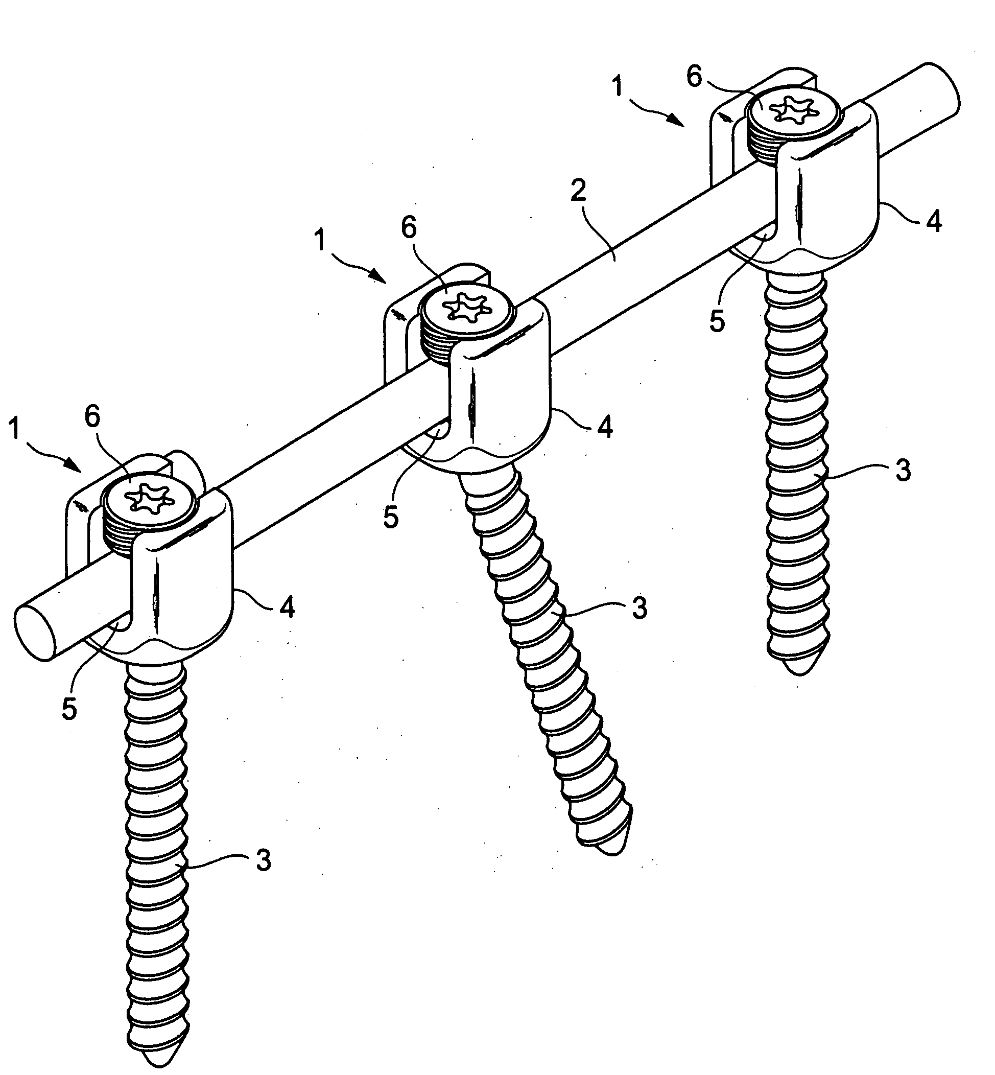
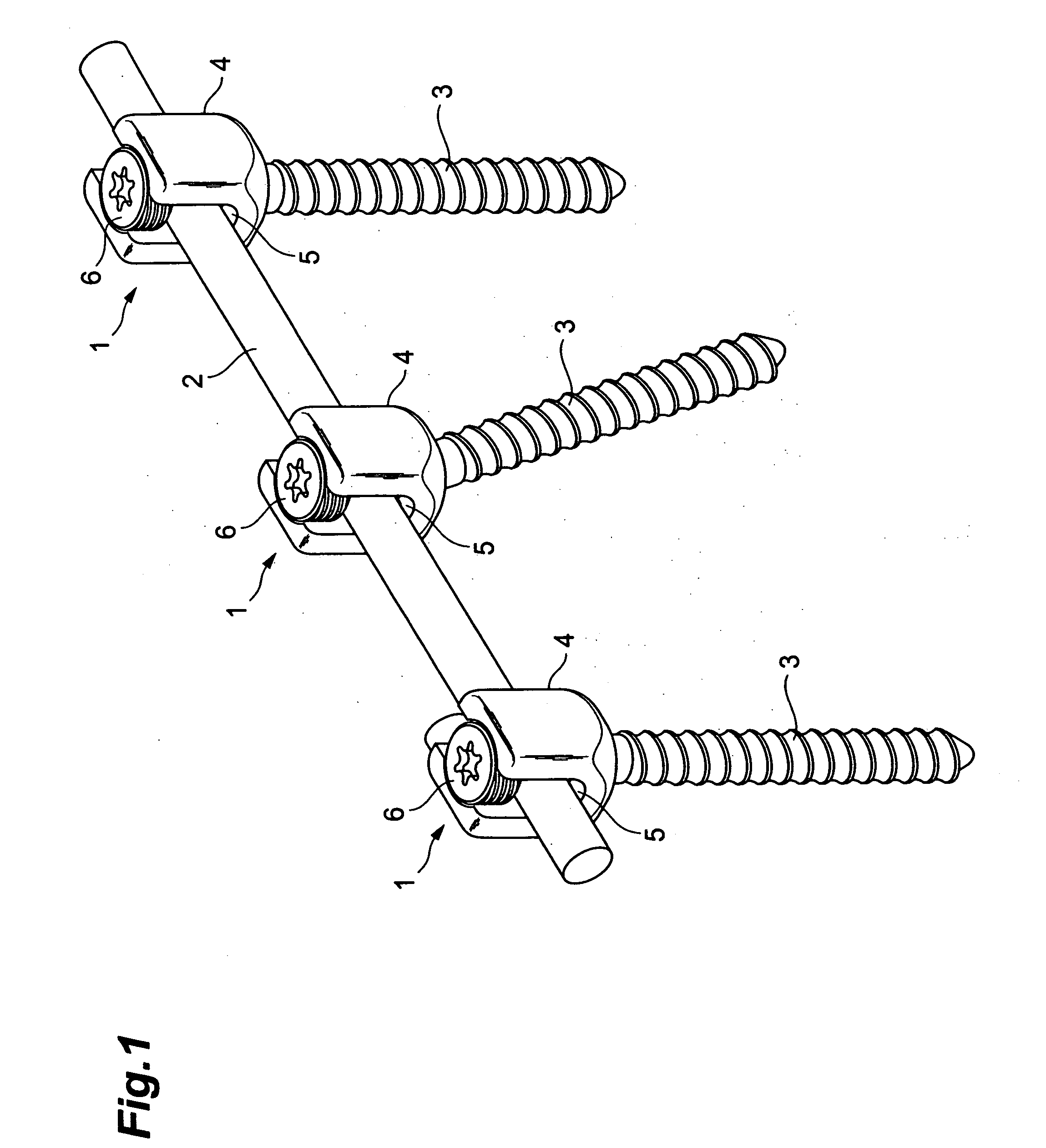
[0030]A vertebra connection member 1 in accordance with the present invention serves to connect and fix a plurality of vertebrae. In actual use, as shown in FIG. 1, a plurality of vertebrae are connected and fixed by fixing a plurality of vertebra connection members 1 to one rod 2.

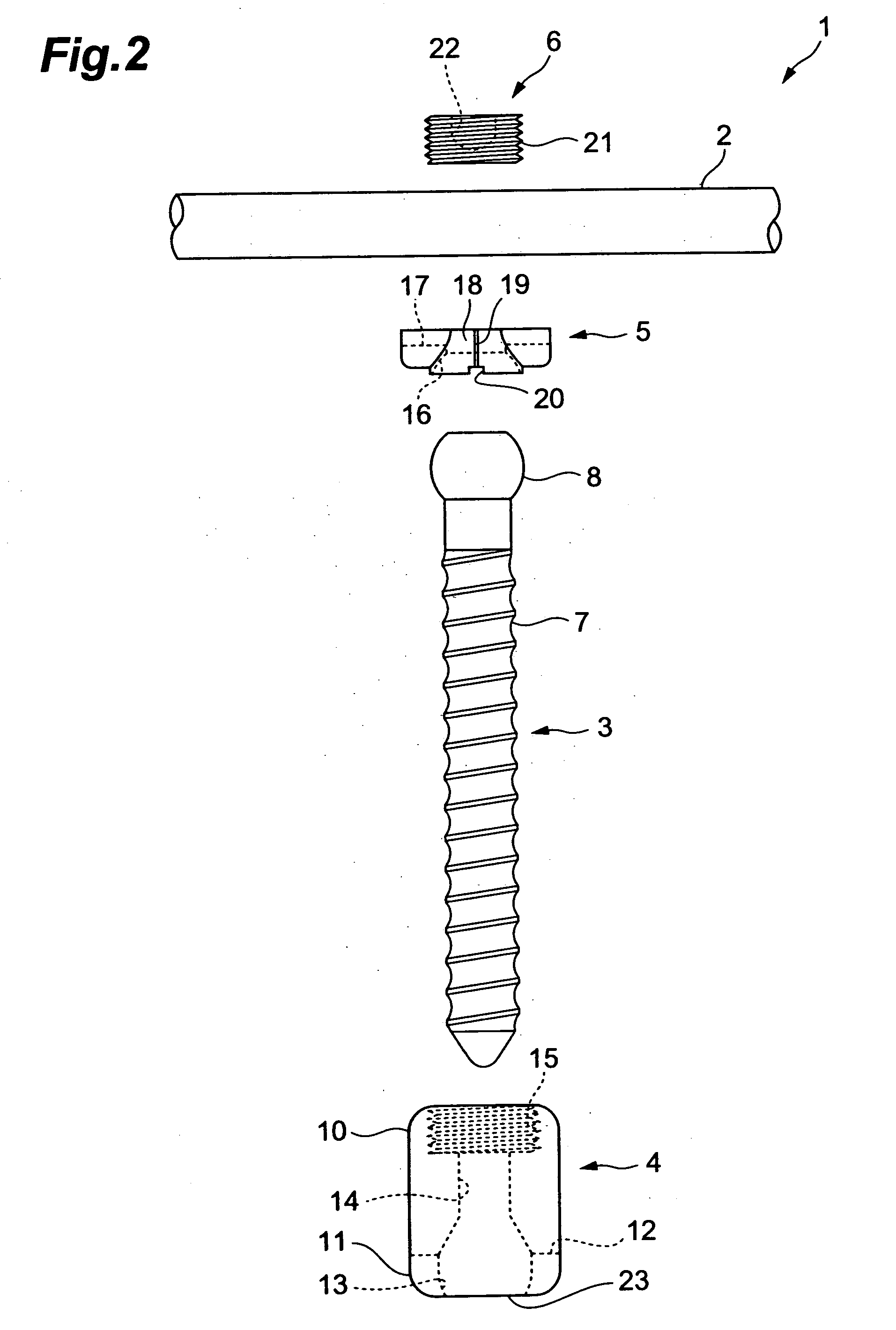
[0031]As shown in FIG. 2 the vertebra connection member 1 comprises a screw member 3 for screwing into a vertebra, a connection member 4 for connecting the screw member 3 and the rod 2, a head section holding member 5 that is inserted between the screw member 3 and rod 2 inside the connection member 4, and a pushing member 6 that is screwed into the connection member 4 and pushes the rod 2 and screw member 3 and fixes them to the connection member 4.

[003...


PUM


Abstract

A vertebra connection member for connecting multiple vertebrae via a rod. The vertebra connection member has a screw member having a spherical head section provided at one end of the screw member and a screw section for being screwed into the vertebra; a connection member into which the screw member is inserted and that connects the screw member and the rod, said connection member having a head support section receiving the head section and supporting the screw member so that the screw member can be tilted, said connection member further having a rod insertion section into which the rod may be inserted; a head section holding member that is inserted between the rod and the head section inside the connection member, said head section holding member having a head holding section for holding the head section and a rod holding section for holding the rod; and a pushing member that pushes the head section toward the head support section via the rod and head section holding member. At least one of the head section, head support section, and head holding section is subjected to surface roughening.

Description

BACKGROUND OF THE INVENTION[0001]1. Field of the Invention[0002]The present invention relates to a vertebra connection member that connects a plurality of vertebrae via a rod.[0003]2. Description of the Related Art[0004]A vertebra connection member described, for example, in Japanese Patent Application Laid-Open No. 2004-097705 is known as a member for connecting a plurality of vertebrae via a rod. In the vertebra connection member, a spherical head section is provided at one end of a screw member to be screwed into a vertebra, this head section is received by a connection member that connects a rod and the screw member, and the screw member is held so that it can be tilted with respect to the connection member. As a result, the connection member can be positioned at a desired angle, and a plurality of vertebrae tilted at different angles can be connected via the rod.SUMMARY OF THE INVENTION[0005]Having analyzed the above-described vertebra connection member, the inventors have disc...

Claims


Application Information

Patent Timeline
Patent Type & Authority Applications(United States)
IPC IPC(8): A61B17/56
CPCA61B17/7037A61B17/7032A61B17/80A61B17/82A61B17/86A61B17/72
Inventor ORIBE, KAZUYATAKAMIDO, HIROSHI
Owner SHOWA IKA KOHGYO
Why Eureka
Try Eureka