
Stent with cover connectors

a technology of stents and connectors, applied in the field of intraluminal support devices, can solve the problems of inconvenient attachment, low resting rate, and intimal hyperplasia that occludes the vessel, and achieve the effect of quick and easy attachmen

Inactive Publication Date: 2008-07-24
DESIGN & PERFORMANCE CYPRUS
View PDF0 Cites 2 Cited by
  • Summary
  • Abstract
  • Description
  • Claims
  • Application Information

AI Technical Summary

Benefits of technology

The invention is about a stent that has a cover to keep it open and secure. The cover can be attached to the stent using a connector that pierces the cover and secures it to the stent. The connector has two sections that form a closed configuration to secure the cover to the stent. The cover can be made from a variety of materials, including expandable tubular body, and the stent can be a conventional self-expanding or balloon-expandable stent. The stent with the cover on it provides a secure and securely attached cover that prevents damage to the cover during attachment.

Problems solved by technology

The healing process frequently causes thrombosis and may lead to intimal hyperplasia that occludes the vessel.
The prior art has employed a number of mechanical and pharmacological strategies to reduce the restenosis rate, but none have been particularly effective.
Although helpful in reducing restenosis, stents do not represent a complete solution.

Method used


Image

  • Stent with cover connectors
  • Stent with cover connectors
  • Stent with cover connectors

Examples


Embodiment Construction

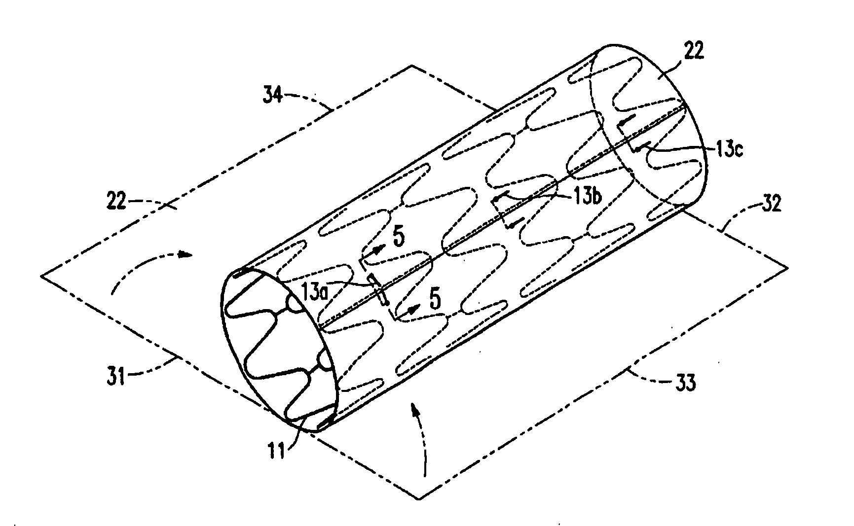
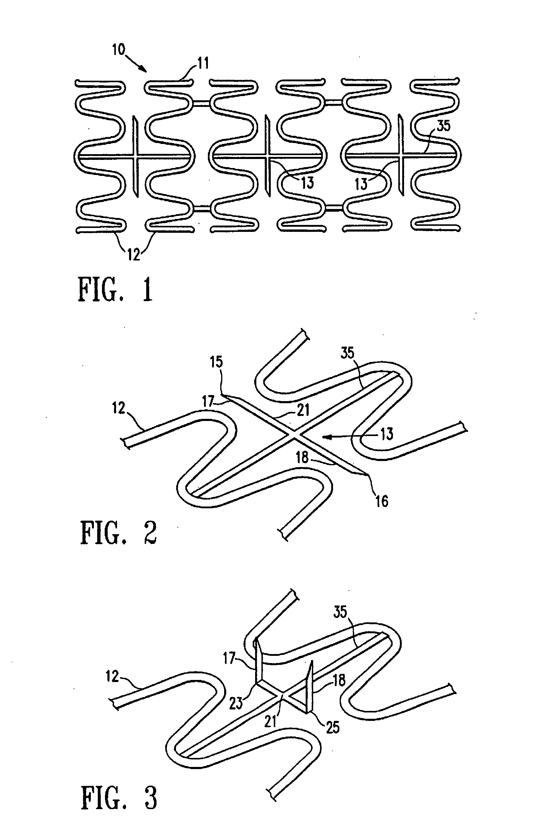
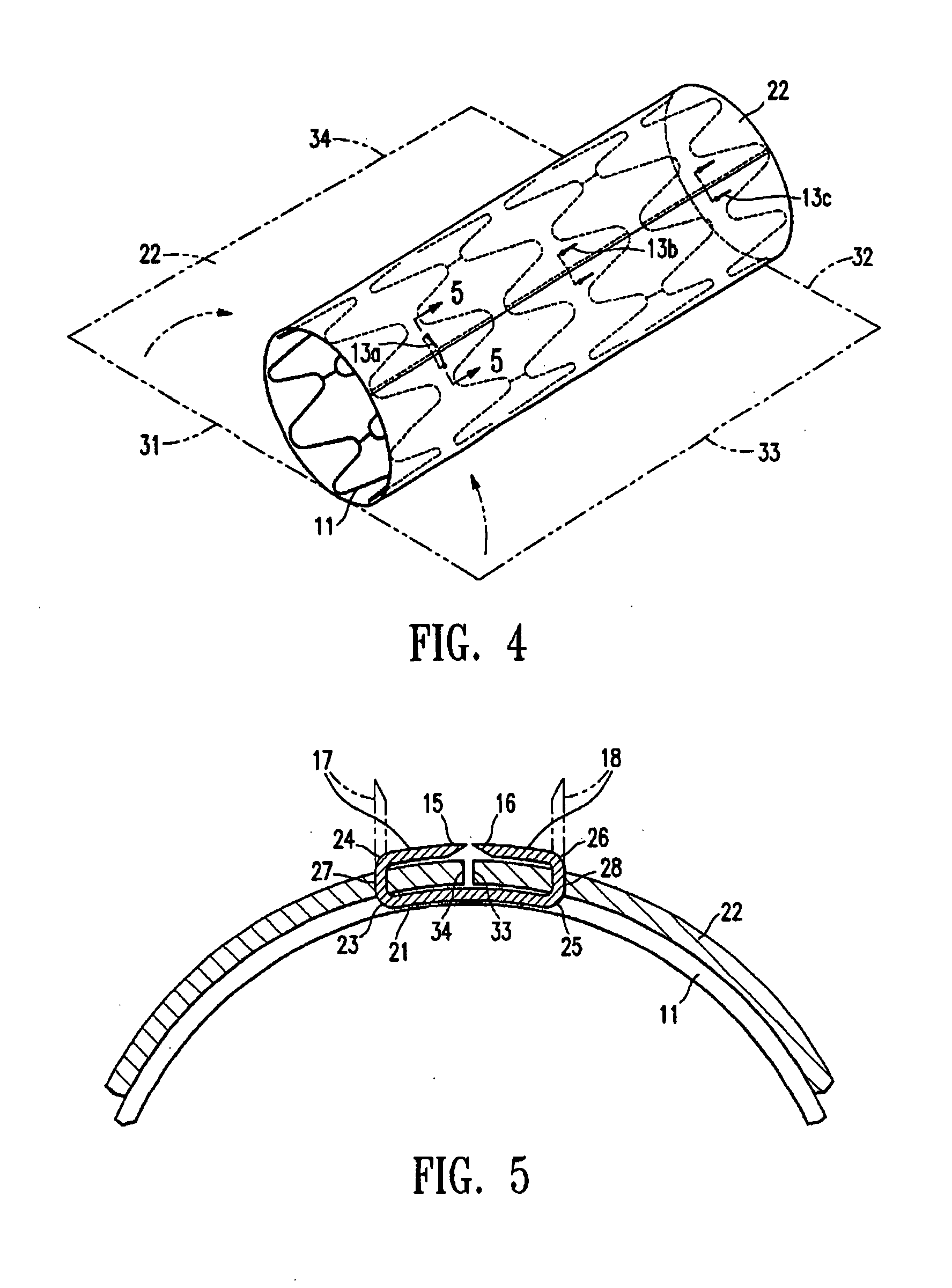
[0040]FIG. 1 is an elevational view of a first embodiment of a stent 10 which embodies features of the invention, comprising an expandable tubular body 11 having first and second ends, a lumen therein, and a framework of spaced apart wall sections 12 defining an open-walled structure, and cover connectors 13 on the tubular body. The cover connectors 13, which are illustrated in more detail in FIG. 2, showing an enlarged view of the connectors shown in FIG. 1, have a first end 15, a second end 16, a first section 17 adjacent to the first end 15, a second section 18 adjacent to the second end 16, and a third section 21 between the first and second sections. The connector 13 is illustrated in FIG. 2 in an open configuration in which the connector is a generally straight, pointed projection attached to the tubular body. FIG. 3 illustrates the connector shown in FIG. 2 bent into a generally U-shaped configuration which facilitates piercing the ends of the connector through a cover to be ...


PUM

PropertyMeasurementUnit
widthaaaaaaaaaa
widthaaaaaaaaaa
widthaaaaaaaaaa

Abstract

A stent suitable for maintaining the patency of a bodily lumen, generally comprising a tubular body configured to facilitate connection of a cover thereto. A stent assembly of the invention generally comprises a stent having cover connectors in contact with a cover to secure the cover to a surface of the stent. The invention also comprises methods of securing a cover to a stent. In a first embodiment, the cover connector on an expandable tubular body has a first section, a second section, and a third section between the first and second sections. The connector has an open configuration, and a closed configuration in which the first section has at least one bend and the second section has at least one bend, so that the first and second sections are bent together and are directed towards the third section therebetween. In a second embodiment, a cover connector is secured to an end of the expandable tubular body, and is configured to fold from an open configuration to a closed configuration in which the connector extends toward a midpoint of the tubular body between the first and second ends of the tubular body and contacts a cover located between the cover connector and a surface of the stent, to secure the cover thereto.

Description

[0001]This application is a continuation-in-part application of U.S. patent application Ser. No. 09 / 522,336, entitled STENT WITH COVER CONNECTORS, filed Mar. 9, 2000, incorporated herein in its entirety by reference.BACKGROUND OF THE INVENTION[0002]This invention relates to the field of intraluminal support devices such as stents and the like. Typically, stents are expandable, tubular metallic devices that are positioned within a patient's vasculature or other body lumen and expanded in order to support a vessel or body lumen at a desired intraluminal location to allow the flow of blood or other body fluids therethrough. Often, the stents are formed from a deformable metal and delivered to the desired intraluminal location by mounting the stent onto an expandable portion, e.g. a balloon, on the distal extremity of a delivery catheter. By advancing the catheter through the body lumen, the stent may be delivered to a desired position and expanded therein by expanding the balloon to an...

Claims


Application Information

Patent Timeline
Patent Type & Authority Applications(United States)
IPC IPC(8): A61F2/82A61F2/06A61F2/84A61L31/00A61F2/90
CPCA61F2/07A61F2230/0034A61F2/91A61F2/915A61F2002/075A61F2002/91533A61F2002/9155A61F2002/91558A61F2002/91566A61F2002/91575A61F2220/0016A61F2220/005A61F2220/0058A61F2220/0075A61F2220/0066A61F2230/0013A61F2/848
Inventor FREIDBERG, CARLOS VONDERWALDECAPUANO, DANIEL
Owner DESIGN & PERFORMANCE CYPRUS
Learn More