
Occlusion perfusion catheter

a perfusion catheter and catheter technology, applied in the field of catheters, can solve the problems of insufficient treatment of prior art devices, large volume of space, and high risk of toxicity, and achieve the effects of minimizing reste minimizing the volume of the space, and minimizing the restnosis of the vessel

Active Publication Date: 2011-11-17
ADVANCED CATHETER THERAPIES INC
View PDF6 Cites 0 Cited by
  • Summary
  • Abstract
  • Description
  • Claims
  • Application Information

AI Technical Summary

Benefits of technology

"The present invention provides an improved agent delivery catheter that can deliver therapy to a site of injury and also allows for visualization of the treatment region. The catheter has a five-lumen design with two occlusion balloons, a space occupying balloon, an agent delivery segment, an aspiration segment, and a visualization segment. The catheter can be used in a minimally invasive insertion technique and can be flushed to improve visualization. The technical effects of the invention include improved delivery of therapy to a treatment region and improved visualization for better guidance and monitoring of the treatment process."

Problems solved by technology

It develops because some of the cells of the vessel wall have been damaged, become “angry” (inflamed) and causes proliferation and migration of muscle cells from the media of the vessel wall into the lumen of the vessel.
Such therapies are particularly susceptible to environmental factors inherent to the delivery process, such as fluid pressure and shear stress, and devices of the prior art do not address these factors adequately.
The problem is that most or all of these have the potential to be toxic when given systemically.
However, when applied regionally to a localized area of “controlled injury” (e.g., in “controlled” or discrete amounts), these agents have the potential of being effective, but non-toxic (or at least significantly less toxic).
The technical problem underlying the present disclosure was therefore to overcome these prior art difficulties by creating devices providing for controlled, focal delivery and subsequent aspiration of therapeutic agents.

Method used


Image

  • Occlusion perfusion catheter
  • Occlusion perfusion catheter
  • Occlusion perfusion catheter

Examples


example 1

General Steps for Using the OPC

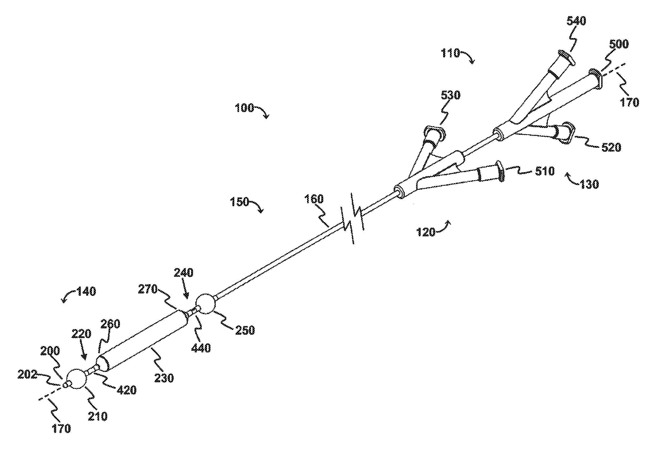
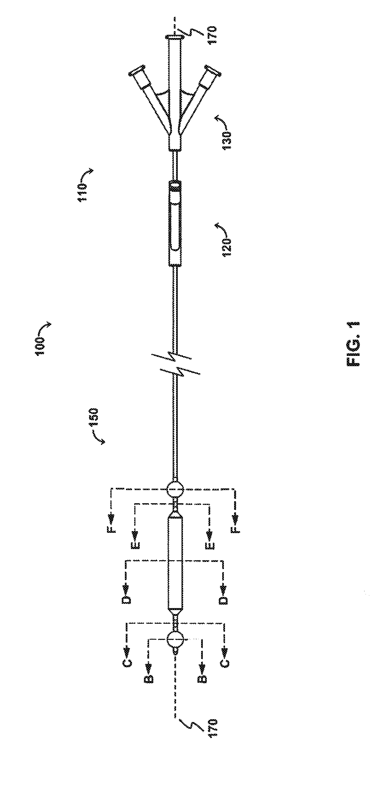
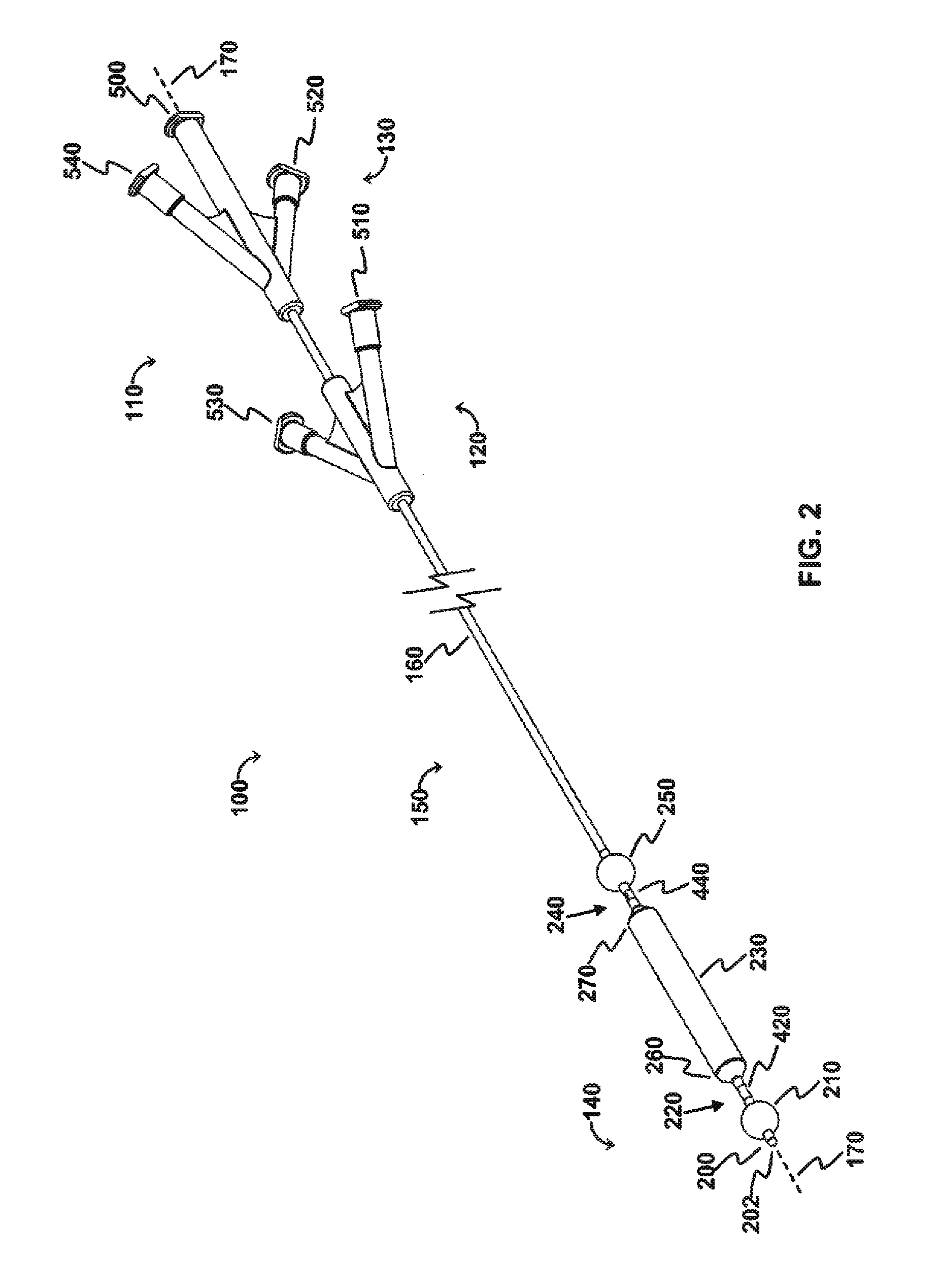
The OPC would be delivered to the treatment site via a minimally invasive insertion technique, over a guidewire, to the treatment area, and the occlusion balloons (210, 250) inflated to isolate the treatment region. Blood and any other fluid trapped between the two inflated occlusion balloons (210, 250) would be aspirated from the treatment region, and the treatment region flushed with saline. The saline would then be aspirated from the treatment region, the space occupying balloon would be inflated, and the agent would be injected into the treatment region. As appropriate, the aspiration lumen could be controlled via the proximal two- or three-way stopcock or check valve to allow the agent to enter the treatment region and prevent the agent from exiting the treatment region prematurely, and further allow selected fluid pressures within the treatment region to be achieved. The space occupying balloon could be optionally deflated, partially, to allow th...

example 2

Simultaneous Perfuse in / Drain Out (Simultaneous Exchange of Fluids in the Isolated Volume)

The OPC would be delivered to the treatment site via a minimally invasive insertion technique, over a guidewire, and the occlusion balloons (210, 250) inflated to isolate the treatment region. The space occupying balloon (230) would be inflated to minimize the treatment volume, with the displaced blood draining out through the evacuation lumen (320). Saline could be used as a flushing agent, or the therapeutic agent could be directly injected in through the perfusion lumen (340), displacing the remainder of the blood. Once the treatment region (60) is filled with the therapeutic agent, a stopcock connected to the device (via the evacuation port (520) would be closed, allowing controlled pressure to be built-up in the treatment region with the continued injection of therapeutic agent, resulting in perfusion into the damaged area of the blood vessel / body lumen. Once treatment is complete, the sto...

example 3

Two-Part Polymeric Agent / Gel Treatment

This modality allows polymerization at the treatment site. The OPC would be delivered to the treatment site via a minimally invasive insertion technique, over a guidewire, and the occlusion balloons (210, 250) inflated to isolate the treatment region. The space occupying balloon (230) would be inflated to minimize the treatment volume, with the displaced blood draining out through the evacuation lumen (320). The remainder of the blood is aspirated out through the evacuation lumen (320), creating a vacuum in the treatment region. A stopcock attached to the evacuation port (520) would be closed, maintaining the vacuum. Once the treatment region is under vacuum, a two part polymeric agent would be injected into the treatment region—part “A” goes in one port (the perfusion lumen (340) for example), while part “B” goes in through the other (the evacuation lumen (320) for example) so that polymerization takes place in the treatment region. Controlled ...


PUM


Abstract

Catheters for occluding, visualizing, irrigating, evacuating, and delivering agents to a treatment area are disclosed. The catheters comprise a catheter body comprising five lumens, first and second occlusion balloons coupled to the catheter body, an optional space-occupying balloon coupled to the catheter body and disposed between the first and second occlusion balloons, and an optional visualization means that enables visualization between the first and second occlusion balloons. Methods for using these catheters are also disclosed. A method comprises inflating the first and second occlusion balloons, inflating the space-occupying balloon, allowing fluid to exit via an evacuation lumen, optionally irrigating or aspirating to facilitate fluid exit via said lumen, and delivering an agent to a treatment area via the agent lumen.

Description

BACKGROUND1. FieldThe present disclosure relates generally to catheter devices and methods for the site-specific delivery of agents to biological spaces in medical procedures. More particularly, the present disclosure relates to catheter devices comprising multiple inflatable means carried by the catheters, with at least one radial opening located between at least a pair of inflatable means. The present disclosure also relates to methods for site-specific delivery of agents into blood vessels (including the blood vessel lumen and the vessel wall) for treatment of said blood vessels and / or other organ systems, as well as methods of visualizing the lumen of said blood vessels and / or other organ systems.2. Description of Related ArtRegardless of the interventional treatment utilized to maintain vessel patency in vascular disease, there will always be restenosis and / or occlusions. The reason for this is that all of these treatment modalities create an intentional “controlled injury” of ...

Claims


Application Information

Patent Timeline
Patent Type & Authority Applications(United States)
IPC IPC(8): A61M25/00A61M1/00A61F2/958
CPCA61B17/12045A61B17/12109A61B17/12136A61B2017/00893A61M5/007A61M25/1011A61M2025/0183A61M2025/1052A61M2025/1097A61B2017/12127A61B5/02154A61B5/02158A61B5/6853A61M1/90A61B1/043A61M2025/1013A61M2025/105A61M39/24A61M2025/1079A61M2025/1093A61M2205/3306A61M2205/3337A61M2205/3344
Inventor TEESLINK, C. REXHOYNS, DIRK V.
Owner ADVANCED CATHETER THERAPIES INC
Learn More