Cognitive wireless communication system

Inactive Publication Date: 2008-07-31
HITACHI LTD
View PDF11 Cites 8 Cited by
  • Summary
  • Abstract
  • Description
  • Claims
  • Application Information

AI Technical Summary

Benefits of technology

[0010]According to the aspect of the present invention, it is possible to prevent the hung-up of communications due to changes in the radio wave condition resu

Problems solved by technology

Therefore, the radio wave condition changes due to frequent displacement of terminals or changes

Method used


Image

  • Cognitive wireless communication system
  • Cognitive wireless communication system
  • Cognitive wireless communication system

Examples


Example

First Embodiment

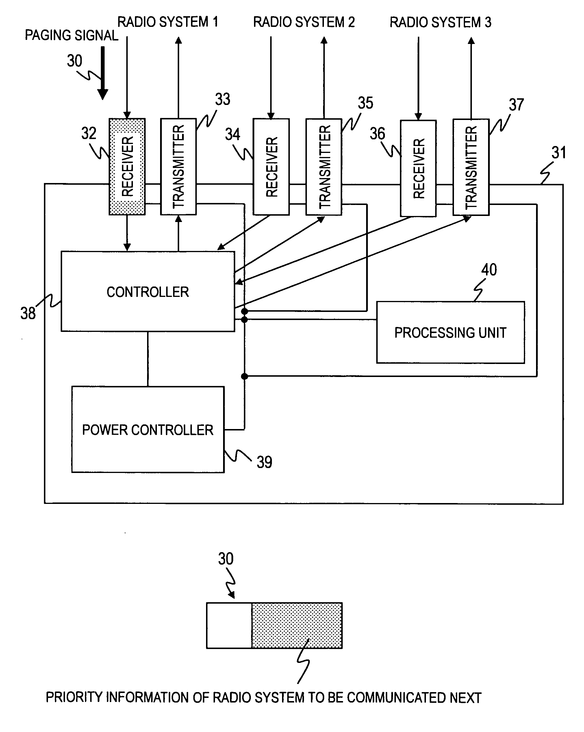
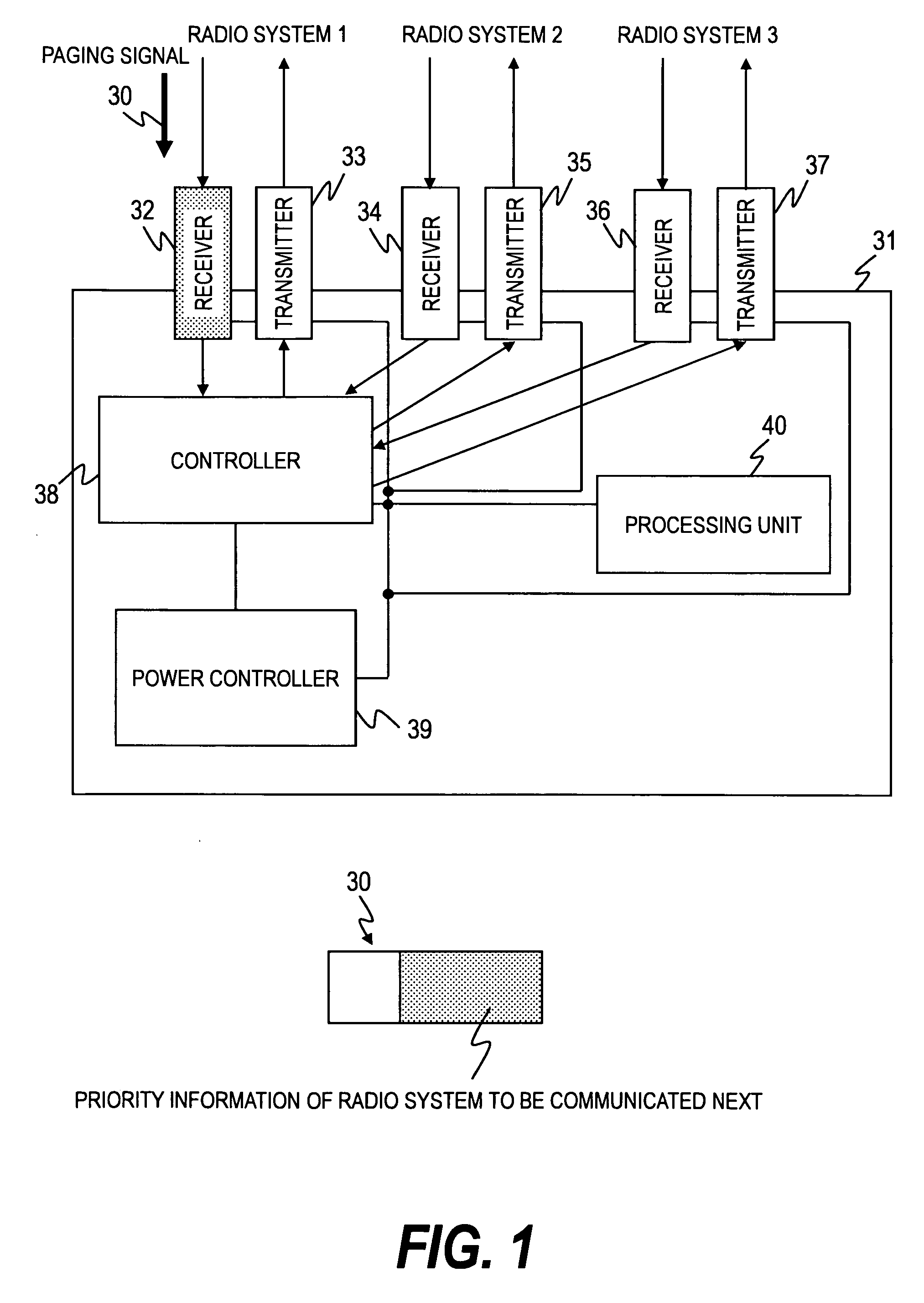
[0026]FIG. 1 is a block diagram showing the configuration of the mobile terminal apparatus used in the multimode radio system of the first embodiment of the present invention. In this embodiment, we will describe the operation of the mobile terminal apparatus having a plurality of radio systems as shown in FIG. 1.

[0027]The paging signal 30 according to the radio system 1 transmitted from the base station side is accompanied by the ID information on which the priority of the radio system to be used hereafter (for example, the following radio system to be used) is added. This paging signal 30 is received by the receiver 32 of the radio system 1 on the terminal side. The controller 38 of the radio system 1 controls the data in the physical layer and the MAC layer. The controller 38 of the radio system 1 decides the radio system for the following communication based on the ID information which includes the priority of this radio system, information on the radio systems a...

Example

Second Embodiment

[0063]According to the first embodiment described above, the base station side decides the priority of the radio system in which the following communication will be made, transmits the information to the terminal by the paging signal 30 of the radio system 1, and the terminal side decided the radio system in which the following communication will be made. However, in the second embodiment which we will describe below, the base station side decides the priority of the radio system in which the following communication will be made, receives the information on the radio system that the terminal side requests to use and the information on the radio system that the terminal side actually can use, and decides the radio system in which the following communication will be made. In this case, the ID information of the radio system in which the following communication will be made decided by the base station side will be transmitted to the terminal side by the paging informat...


PUM


Abstract

To prevent a hung-up of communications due to changes in a radio wave condition resulting from frequent displacement of the terminals and changes in a number of the terminals, and to realize switching of the radio systems adapting to the radio condition. A radio communication system comprising: a base station for providing a plurality of radio systems, and terminals for communicating with the base station through the plurality of radio systems. The base station decides a priority of the radio system on which the each terminal will communicate thereafter and transmits paging signals of one of the plurality of radio systems which includes information on the decided priority to the each terminal.

Description

CLAIM OF PRIORITY[0001]The present application claims priority from Japanese patent application JP 2007-20357 filed on Jan. 31, 2007, the content of which is hereby incorporated by reference into this application.BACKGROUND OF THE INVENTION[0002]The present invention relates to a radio communication system in which a terminal communicates by using a plurality of radio systems, and in particular a high-speed switching technology between a plurality of radio communication systems and a cognitive communication technology for improving the time use efficiency of frequency.BACKGROUND OF THE INVENTION[0003]The band of 6 GHz or less convenient for mobile communication systems (VHF, UHF, low micro band) is now used densely for communication by the third generation mobile phone, wireless LAN and the like and the tight condition of frequency is getting increasingly serious. Under such a situation, in order to use effectively and efficiently radio wave whose availability is getting increasingl...

Claims


Application Information

Patent Timeline
IPC IPC(8): H04B7/00H04W68/00H04W72/10H04W88/10
CPCH04W68/00H04W88/10H04W72/10H04W72/56
Inventor YAMAOKA, RYOUJIYAMAMOTO, JUNJIWAKAYAMA, KOJIHANAOKA, SEISHIMORISHIGE, TAKEHIROYANO, MASASHISUZUKI, TOSHIAKIYOSHIZAWA, SATOSHI
Owner HITACHI LTD
Why Eureka
Try Eureka