Apparatus and method for camera calibration, and vehicle

a technology for cameras and apparatuses, applied in the field of apparatus and methods for camera calibration, and vehicles, can solve the problems of difficult measurement or estimation of accurate conversion parameters, driver will find great difficulty in accurately grasping distances, and errors are inevitabl

Inactive Publication Date: 2008-08-07
SANYO ELECTRIC CO LTD
View PDF6 Cites 61 Cited by
  • Summary
  • Abstract
  • Description
  • Claims
  • Application Information

AI Technical Summary

Problems solved by technology

Inconveniently, however, a rear camera is typically installed to point obliquely downward; thus, if the image shot with it is displayed unprocessed, the driver will find great difficulty grasping the distance accurately.
Errors are inevitable, however, between the angle and height as designed and those at which the camera is actually installed on a vehicle.
Thus, it is often difficult to measure or estimate accurate conversion parameters.
That is, it is troublesome to set up an environment for calibration, increasing the burden imposed by calibration operation as a whole.
The farther away from the calibration pattern, however, the greater the effect of errors in the coordinates set for the four characteristic points 321 to 324, and thus the lower the accuracy of coordinate conversion.
Even this method requires that a coordinate system (two-dimensional world coordinate system) common to the plurality of images be set, and thus provides no solution to the trouble with setting up the calibration environment.

Method used


Image

  • Apparatus and method for camera calibration, and vehicle
  • Apparatus and method for camera calibration, and vehicle
  • Apparatus and method for camera calibration, and vehicle

Examples


example 1

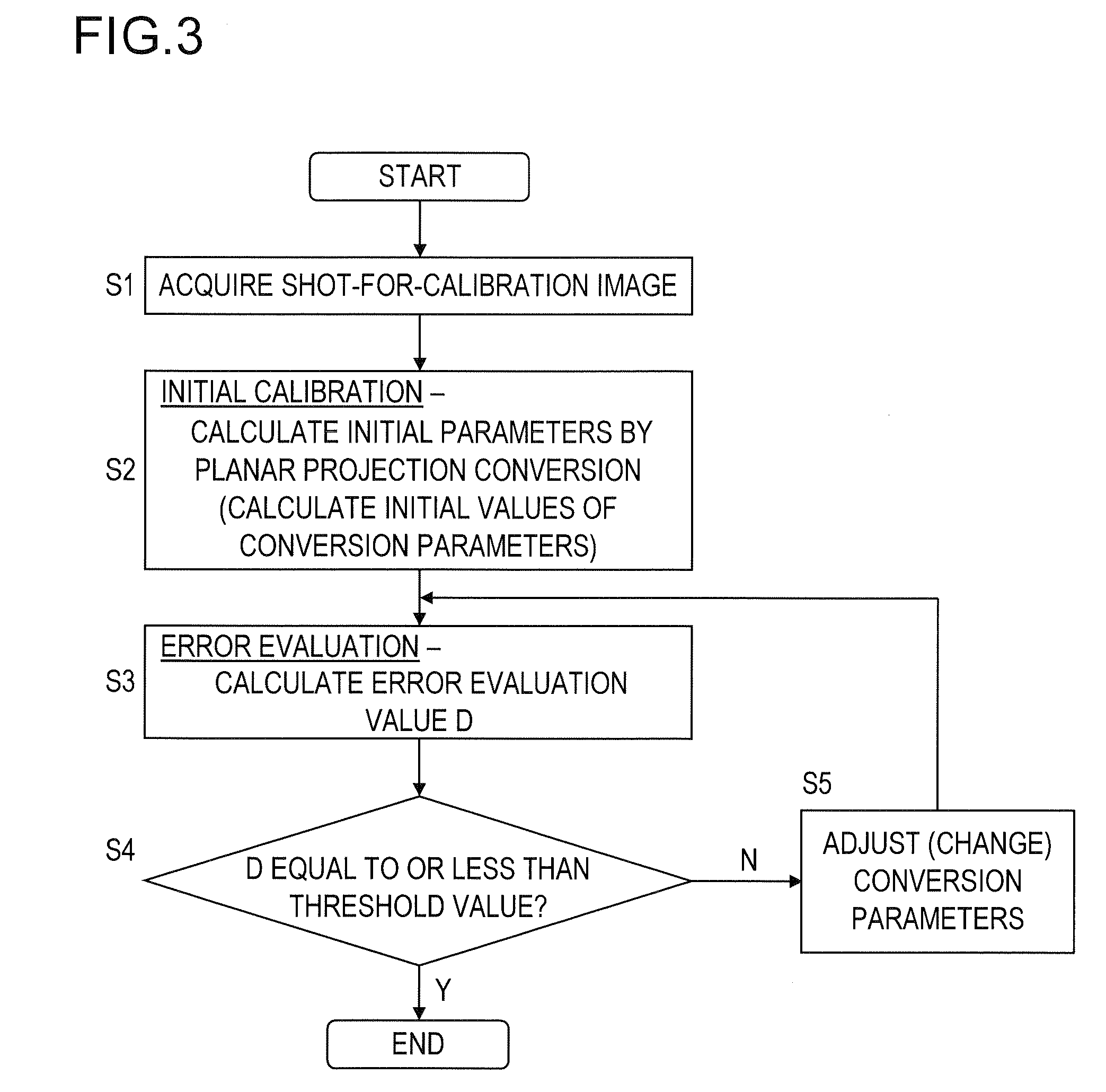
[0050]First, Example 1 will be described. FIG. 3 is a flow chart showing the procedure of conversion parameter calibration processing in Example 1. The operation in step S1 is executed by the camera 1 (and the image processing apparatus 2); the operations in steps S2 to S5 are executed by the image processing apparatus 2.

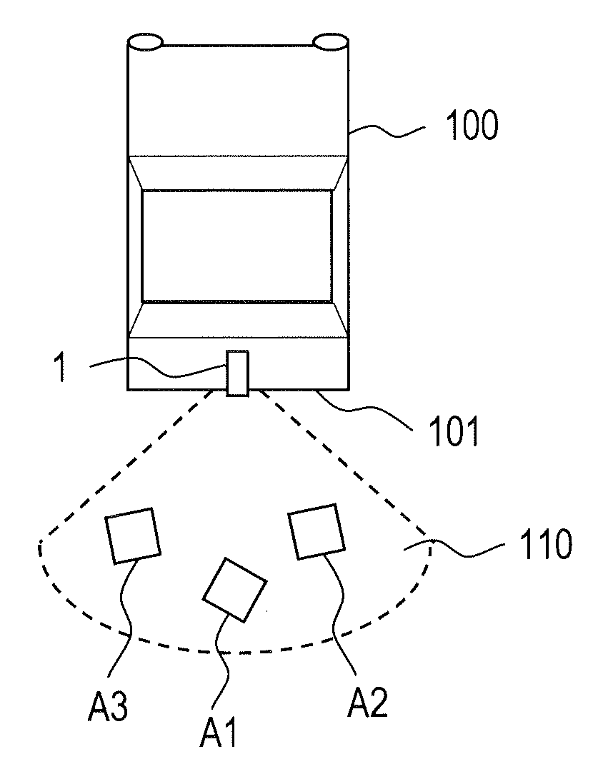
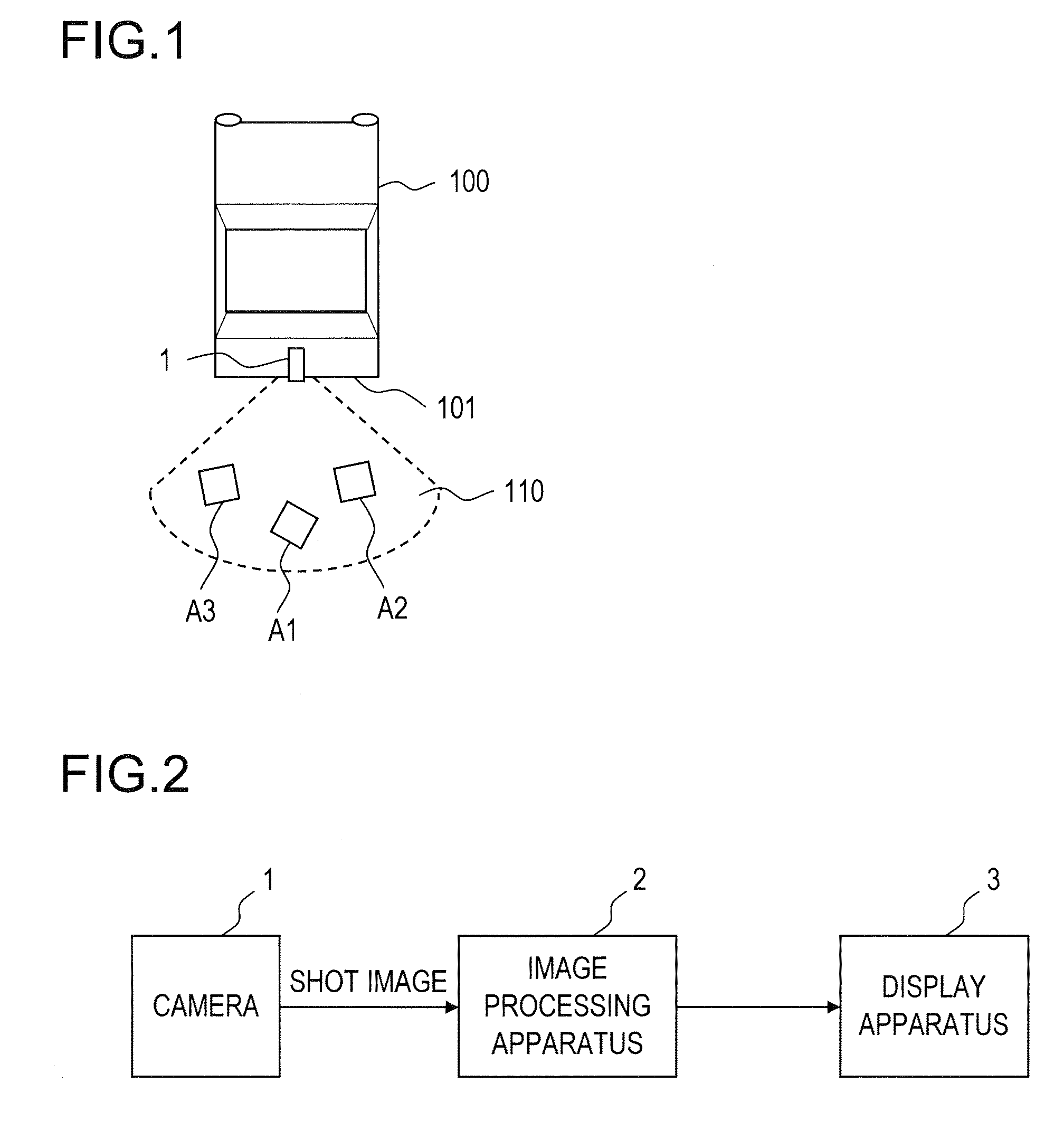
[0051]First, in step S1, the calibration patterns A1 to A3 arranged within the shooting area as described above are shot with the camera 1 to obtain a shot image. This shot image is called the “shot-for-calibration image”. In FIG. 4A, reference sign 121 indicates the shot-for-calibration image. In FIGS. 4A to 4C, part of the bumper 101 appears on the images.

[0052]Next, in step S2, initial calibration is performed. In the initial calibration, planar projection conversion is performed by use of any one of the three calibration patterns A1 to A3 included in the shot-for-calibration image to calculate initial parameters, which will be dealt with as the initial values of...

example 2

[0072]Next, Example 2 will be described. FIG. 6 is a flow chart showing the procedure of conversion parameter calibration processing in Example 2. The conversion parameter calibration processing in Example 2 includes operations in steps S1 to S5 and an operation in step S6. The operation in step S6 is executed by the image processing apparatus 2.

[0073]The operations in steps S1 to S5 are the same as in Example 1. Accordingly, no overlapping description of them will be repeated. In Example 2, if, in step S4, the error evaluation value D is equal to or less than the predetermined threshold value, it is judged that the homography matrix H has now been optimized through the repeated calculations in steps S3 to S5, and an advance is made to step S6.

[0074]Installed for the check for safety behind the vehicle 100, the camera 1 is typically so fitted as to shoot behind the vehicle 100 evenly to the right and left with no inclination. Since installation errors are inevitable, however, a shot...

example 3

[0083]Next, Example 3 will be described. FIG. 9 is a flow chart showing the procedure of conversion parameter calibration processing in Example 3. In the conversion parameter calibration processing in Example 3, initial parameters are calculated by perspective projection conversion. The operations after the calculation of the initial parameters are the same as those in Example 1 or 2. In the conversion parameter calibration processing shown in FIG. 9, the operations after the calculation of the initial parameters are the same as those in Example 2; they may instead be the same as those in Example 1 (that is, step S6 may be omitted).

[0084]The conversion parameter calibration processing shown in FIG. 9 includes operations in steps S11 and S12 and operations in steps S3 to S6. The operations in steps S3 to S6 are the same as in Example 2.

[0085]First, in step S11, initial calibration is performed. In the initial calibration, initial parameters are calculated by perspective projection co...


PUM


Abstract

A camera calibration apparatus has a parameter deriver adapted to find parameters for projecting an image shot with a camera onto a predetermined surface. The parameter deriver finds the parameters based on a shot-for-calibration image from the camera, and the shot-for-calibration image includes a plurality of calibration patterns of previously known shapes arranged at different positions within the shooting area of the camera.

Description

[0001]This nonprovisional application claims priority under 35 U.S.C. §119(a) on Patent Application No. 2007-022630 filed in Japan on Feb. 1, 2007, the entire contents of which are hereby incorporated by reference.BACKGROUND OF THE INVENTION[0002]1. Field of the Invention[0003]The present invention relates to a camera calibration apparatus and a camera calibration method for realizing calibration processing needed to project an image shot with a camera onto a predetermined surface. The invention also relates to a vehicle that employs such an apparatus and a method.[0004]2. Description of Related Art[0005]In recent years, with increasing awareness for safety, more and more vehicles such as automobiles have come to be equipped with cameras (vehicle-mounted cameras). Especially popular are rear cameras that are fitted to help check for safety behind vehicles. The image shot with such a rear camera is displayed on a display apparatus incorporated in a car navigation system or the like, ...

Claims


Application Information

Patent Timeline
Patent Type & Authority Applications(United States)
IPC IPC(8): H04N17/00
CPCG06T7/0018H04N17/002G06T2207/30252G06T7/80
Inventor ISHII, YOHEIKANO, HIROSHIOKUDA, KOZOASARI, KEISUKE
Owner SANYO ELECTRIC CO LTD
Why Eureka
Try Eureka