Magnetic latch mechanism

a latch mechanism and magnet technology, applied in the construction details of electrical devices, instruments, portable computers, etc., can solve the problems of increasing affecting the overall cost of the electronic device, and affecting the reliability of the latch mechanism

Inactive Publication Date: 2008-08-07
APPLE INC
View PDF22 Cites 305 Cited by
  • Summary
  • Abstract
  • Description
  • Claims
  • Application Information

AI Technical Summary

Benefits of technology

[0006]In one or more embodiments, the invention relates to an electronic device having a magnetic latch mechanism. The electronic device includes a first electronic assembly and a second electronic assembly pivotally connected with the first electronic assembly. The electronic device also includes magnetic means for providing an uneven magnetic flux with respect to at least two sides of the magnetic means. A first side of the magnetic means has a first magnetic flux that is higher in intensity relative to a second magnetic flux associated with a second side of the magnetic means. The magnetic means is captured by the first electronic assembly. The electronic device further includes attraction means for magnetically attracting the magnetic means. The attraction means is captured by the second electronic assembly. The attraction means is configured to be coupled with the first magnetic flux when the first electronic assembly is in a closed position with respect to the second electronic assembly such that there is mutual attraction between the attraction plate and the Halbach array in the closed position.
[0007]In one or more embodiments, the invention relates to an electronic device having a magnetic latch mechanism. The electronic device includes a first electronic assembly and a second electronic assembly pivotally connected with the first electronic assembly. The electronic device also includes a magnetic unit captured by the first electronic assembly. The magnetic unit is configured to provide a first magnetic flux in a first direction. The electronic device further includes an attraction plate captured by the second electronic assembly. The attraction plate is configured to be coupled with the first magnetic flux when the first electronic assembly is in a closed position with respect to the second electronic assembly such that there is mutual attraction between the attraction plate and the Halbach array in the closed position.

Problems solved by technology

However, the latch and catch components may be vulnerable to impact damage and may pose significant reliability issues.
However, the additional cost of the high performance material disadvantageously increases the overall cost of the electronic device.
Further, such a latch mechanism occupies some amount of space and may need to be housed in gaps, voids, or recesses in the display assembly and / or the base assembly.
These gaps, voids, or recesses may significantly compromise the structure and / or aesthetics of the electronic device and possibly allow debris and / or moisture to cause damage to the electronic device.
Both of these alternative mechanisms typically require a large form factor to implement and therefore may be undesirable to users from an aesthetic point of view.
However, many other components of the electronic device may be sensitive to magnetic effects.
As such, the use of magnets may complicate the design and arrangement of components inside the electronic device, which may require for example magnetic shielding to protect these sensitive components.
Installation of magnetic shields may incur increased manufacturing cost as well as consume some of the internal space of the electronic device, resulting in an undesirably bulky final product.

Method used


Image

  • Magnetic latch mechanism
  • Magnetic latch mechanism
  • Magnetic latch mechanism

Examples


Embodiment Construction

[0016]The present invention will now be described in detail with reference to a few embodiments thereof as illustrated in the accompanying drawings. In the following description, numerous specific details are set forth in order to provide a thorough understanding of the present invention. It will be apparent, however, to one skilled in the art, that the present invention may be practiced without some or all of these specific details. In other instances, well known process steps and / or structures have not been described in detail in order to not unnecessarily obscure the present invention.

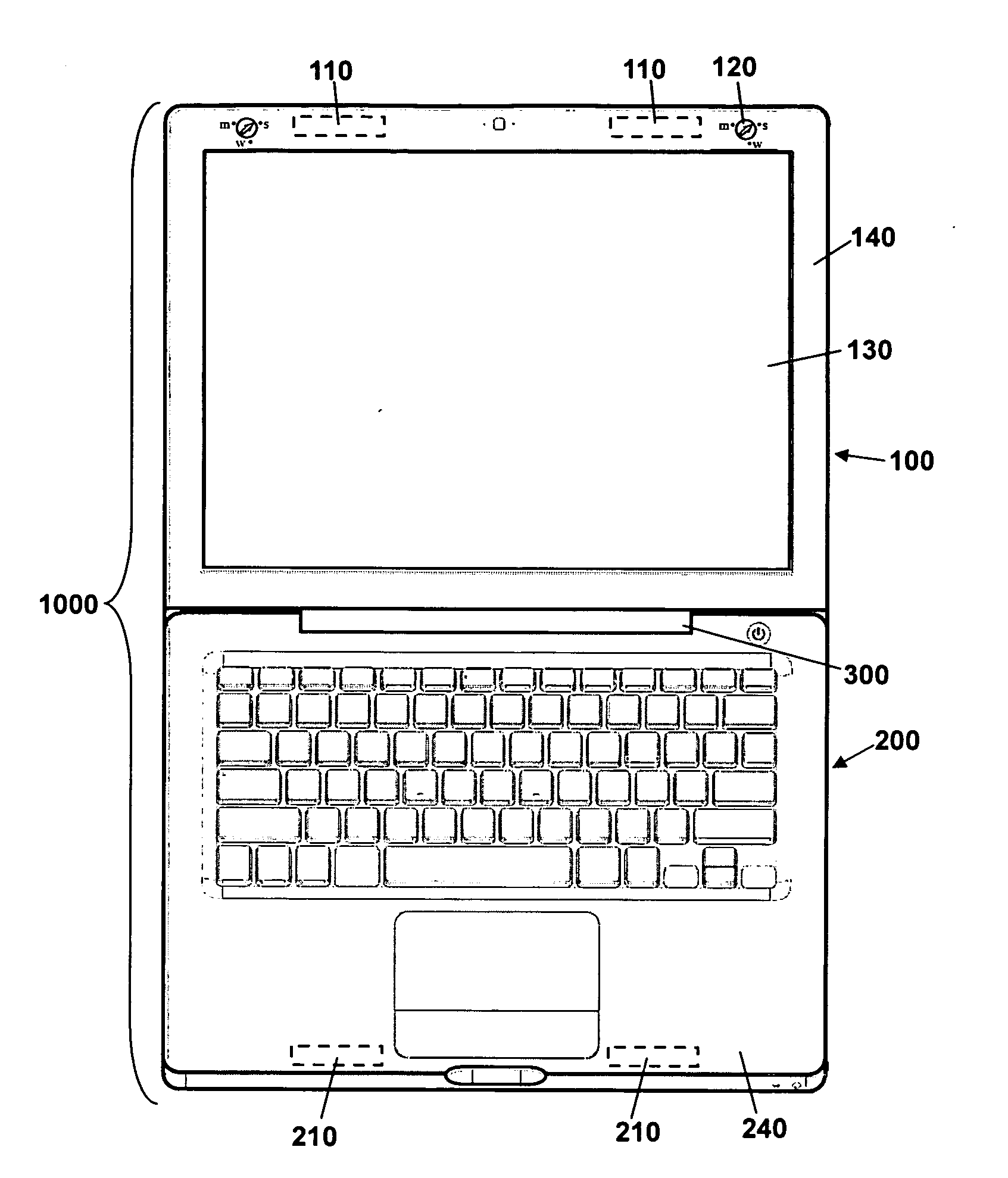
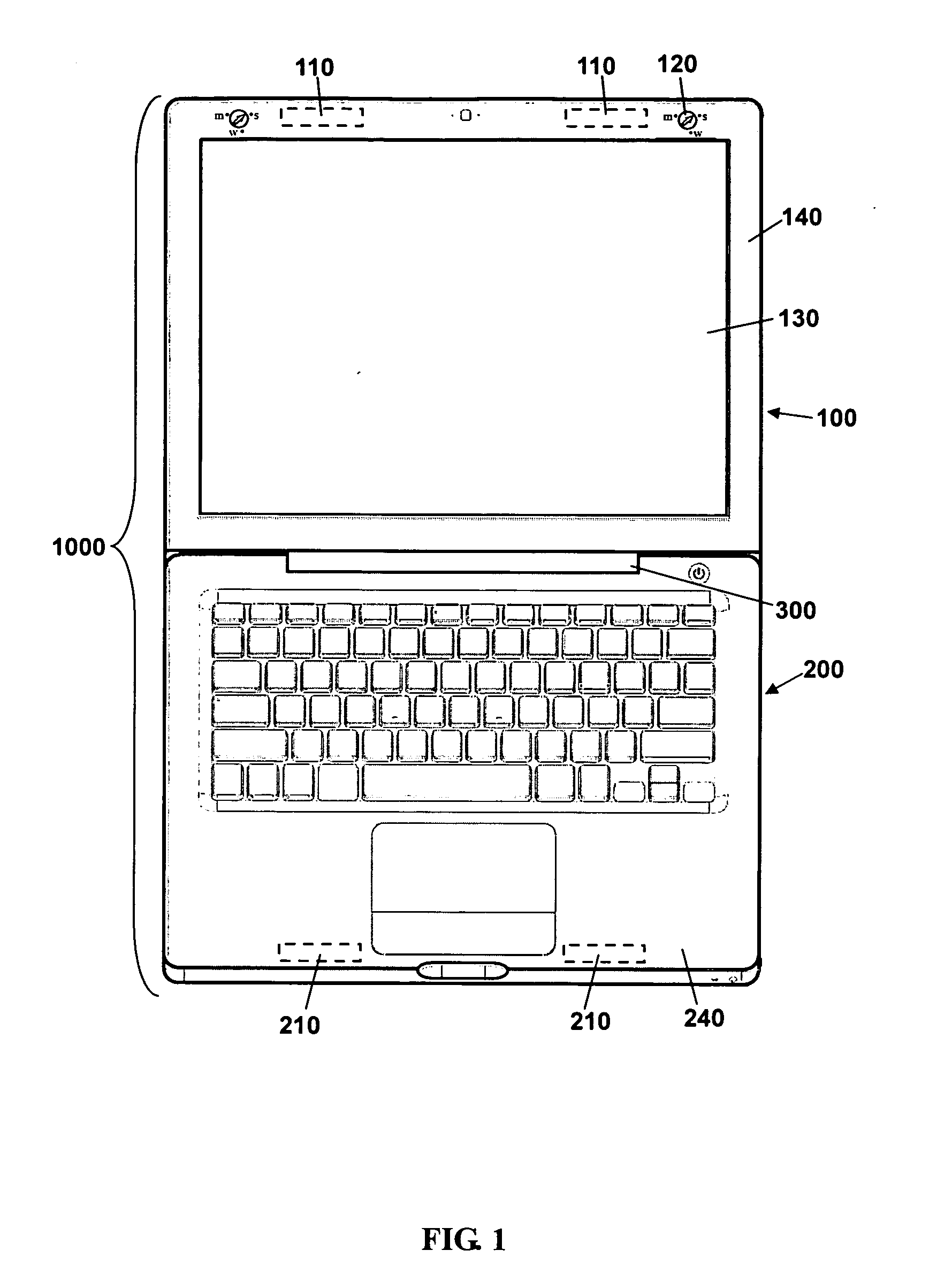
[0017]FIG. 1 shows an illustrative representation of an electronic device 1000 and a magnetic latch mechanism in accordance with one or more embodiments of the present invention. In accordance with one or more embodiments of the present invention, as illustrated in FIG. 1, electronic device 1000 is a portable computing device. However, electronic device 1000 may represent any electronic device (such...


PUM


Abstract

A magnetic latch mechanism for latching a first electronic assembly to a second electronic assembly. The magnetic latch mechanism includes a Halbach array captured by the first electronic assembly. The Halbach array is configured to provide a first magnetic flux in a first direction. The magnetic latch mechanism further includes an attraction plate captured by the second electronic assembly. The attraction plate is configured to be coupled with the first magnetic flux when the first electronic assembly is in a closed position with respect to the second electronic assembly such that there is mutual attraction between the attraction plate and the Halbach array in the closed position.

Description

BACKGROUND OF THE INVENTION[0001]An electronic device that includes a display such as a notebook computer, media player, game device, or navigation device may include a display assembly and a base assembly. Typically, an edge of the display assembly is connected with the base assembly by one or more hinges or clutches so that the display assembly can be pivoted open to reveal the display screen of the display assembly to the user or closed to protect the display screen. To ensure that the electronic device stays closed, the electronic device may further include a latch mechanism for securing the display assembly in the closed position.[0002]Conventionally, the latch mechanism may include a latch and a catch for securing the display assembly in the closed position. However, the latch and catch components may be vulnerable to impact damage and may pose significant reliability issues. To better withstand impact and wear, the latch and catch and other related moving components may be ma...

Claims


Application Information

Patent Timeline
Patent Type & Authority Applications(United States)
IPC IPC(8): H01H9/22H05K7/16
CPCG06F1/1679G06F1/1616
Inventor LIGTENBERG, CHRIS A.DEGNER, BRETT WILLIAMBANKO, JOSHUA
Owner APPLE INC
Why Eureka
Try Eureka