
Original-document illumination apparatus, image reading apparatus, color-original-document reading apparatus and image forming apparatus

a technology of illumination apparatus and original documents, applied in the field of original, can solve the problems of inability to use such apparatuses as a higher-speed reading apparatus and a large-type apparatus, inability to contradict the promotion of energy-saving products, and possible uneven distribution of illuminance, so as to improve the quality of reading original documents and reduce the effect of illuminance intensity distribution

Inactive Publication Date: 2008-03-13
RICOH KK
View PDF6 Cites 11 Cited by
  • Summary
  • Abstract
  • Description
  • Claims
  • Application Information

AI Technical Summary

Benefits of technology

The present invention relates to an original-document illumination apparatus for improving the quality of reading original documents and images. The apparatus includes a lens array and a light-source unit with multiple light-emitting elements that illuminate the original-document. The lens array has multiple convergent lenses that radiate the light from the light-emitting elements onto the illuminated face. The light-emitting elements may be white light emitting diodes that emit light of different colors. The lenses may have a non-circular arc shape in cross-section, and the light-incoming and outgoing planes may have a flat and curved shape, respectively. The lens array may be made of plastic. The apparatus may be used in image reading apparatus, color-original-document reading apparatus, and image forming apparatus.

Problems solved by technology

Accordingly, LEDs can be used in such apparatuses as a lower-speed reading apparatus and a compact-type reading apparatus, but cannot be used in such apparatuses as a higher-speed reading apparatuses and a large-type apparatus.
In this case, however, the light of each LED spreads so widely as to lessen the efficiency and to contradict the promotion of energy saving products.
However, the light emitted from the round type LED is irradiated in a direction at a narrow angle, so that an uneven distribution of illuminance may possibly occur in the main-scanning direction.
Such a method, however, has a problem.
In this method, among the light emitted from the LEDs to the sub-scanning-direction cross section, most of the light emitted at an oblique angle to the optical axis is not used as an illuminating light, that is, most of the light is wasted.
The resultant complex structure brings about an increase in manufacturing costs.

Method used


Image

  • Original-document illumination apparatus, image reading apparatus, color-original-document reading apparatus and image forming apparatus
  • Original-document illumination apparatus, image reading apparatus, color-original-document reading apparatus and image forming apparatus
  • Original-document illumination apparatus, image reading apparatus, color-original-document reading apparatus and image forming apparatus

Examples


first embodiment

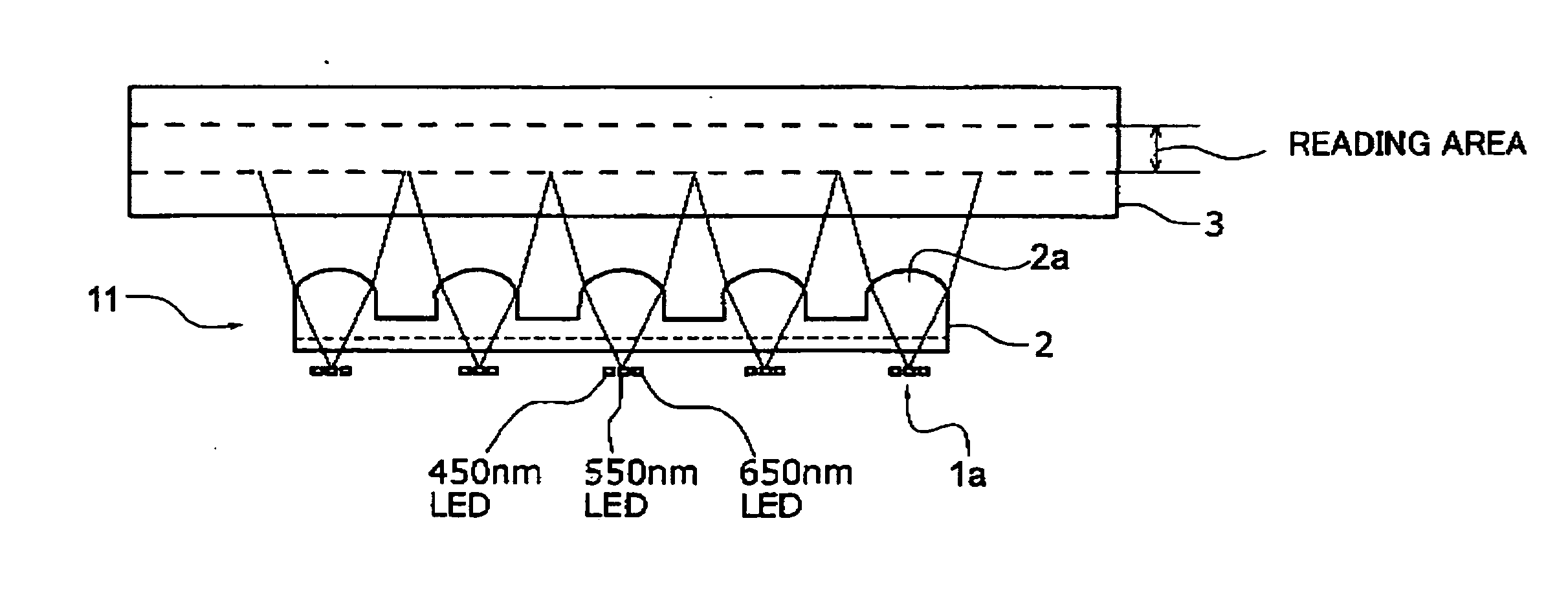
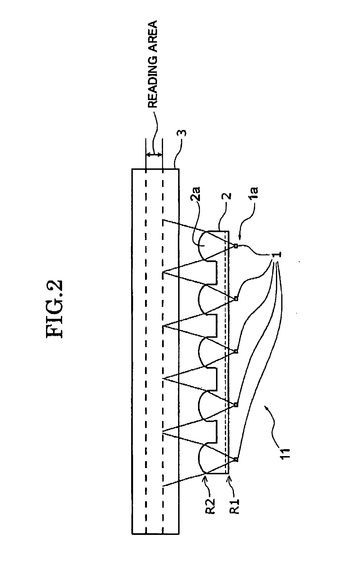
[0042]An original-document illumination apparatus according to a first embodiment of the present invention includes a two-dimensional illuminated face that extends in the main-scanning direction and sub-scanning direction. The original-document illumination apparatus also includes a light-source unit. The light-source unit has a plurality of light-emitting elements arranged, at predetermined intervals, in the main-scanning direction, and is movable in the sub-scanning direction. In addition, the original-document illumination apparatus includes a lens array disposed between the illuminated face and the light-source unit. The lens array is formed by arranging a plurality of convergent lenses. The luminous flux emitted from each of the light-emitting elements of the light-source unit is radiated, through the lens array, to the illuminated face.

[0043]In the first embodiment, the lenses in the lens array are arranged along the main-scanning direction at predetermined intervals. In addit...

second embodiment

[0048]An image reading apparatus into which the original-document illumination apparatus according to the first embodiment is incorporated is also a preferred embodiment of the present invention. In addition, a preferable original-document illumination apparatus in the image reading apparatus according to this embodiment is suitable for reading an original-document in color. The image reading apparatus according to this embodiment is an image reading unit 200 in the example shown in FIG. 7.

third embodiment

[0049]An image forming apparatus into which the image reading apparatus according to the second embodiment is incorporated is also a preferred embodiment of the present invention. FIG. 7 shows an example of the image forming apparatus according to this embodiment.

[Components of Examples]

[0050]Hereinafter, descriptions will be given of components of Examples 1 and 2 for further specifically describing the first embodiment.

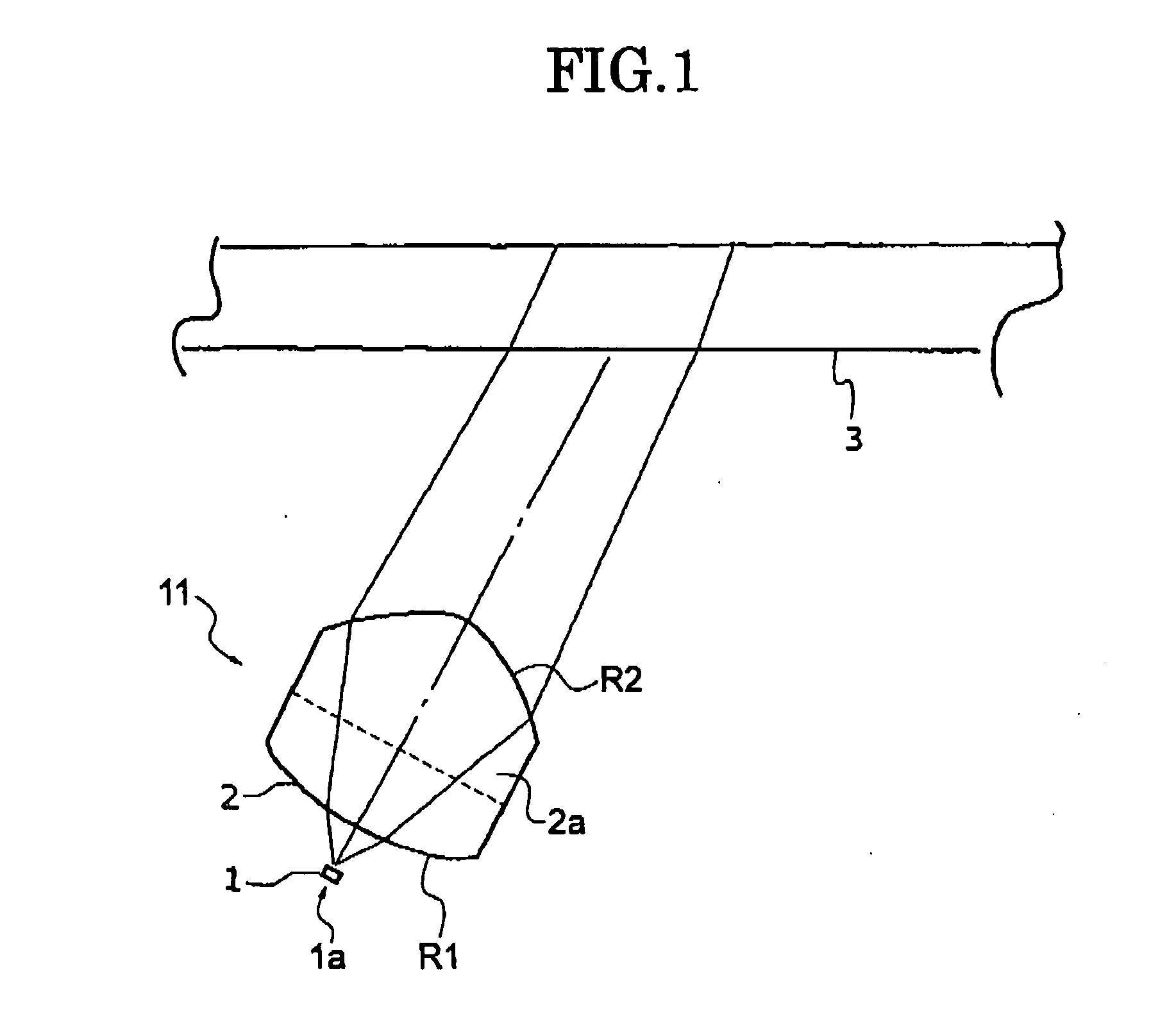
[0051]FIG. 1 is a view showing a sub-scanning-direction cross section including a light-emitting element 1 of a light-source unit 1a. FIG. 1 shows a single one of a plurality of lenses 2a of a lens array 2. Additionally, in the Examples below, each light-emitting element 1 is disposed correspondingly to each lens 2a.

[0052]In the example shown FIG. 1, the scanning optical system has to optically read the illuminated face, so that the illuminated face—a contact glass 3—is illuminated obliquely from below, and is read form below. Additionally, in FIG. 1, the light emi...


PUM


Abstract

An original-document illumination apparatus includes an illuminated face on which an original-document is placed. The original-document illumination apparatus also includes a light-source unit having a plurality of light-emitting elements which are arranged along the main-scanning direction of the original-document and which illuminate the original-document. The light source unit is movable in a sub-scanning direction that is orthogonal to the main-scanning direction. In addition, the original-document illumination apparatus includes a lens array disposed between the illuminated face and the light-source unit, and having a plurality of convergent lenses. A luminous flux from each of the light-emitting elements of the light-source unit is radiated onto the illuminated face through each of the lenses of the lens array.

Description

PRIORITY CLAIM[0001]The present application is based on and claims priority from Japanese Application Number 2006-248685, filed Sep. 13, 2006, the disclosure of which is hereby incorporated by reference herein in its entirety.BACKGROUND OF THE INVENTION[0002]1. Field of the Invention[0003]The present invention relates to an original-document illumination apparatus used for digital copiers and image scanners. The invention, in particular, relates to an original-document illumination apparatus which employs a light emitting diode as a light source. The invention also relates to a color-original-document reading apparatus and an image reading apparatus which employ the original-document illumination apparatus. The invention furthermore relates to an image forming apparatus which employs the color-original-document reading apparatus and the image reading apparatus.[0004]2. Description of Related Art[0005]Development of light emitting diodes (LEDs) has been advanced recently, and LEDs ha...

Claims


Application Information

Patent Timeline
Patent Type & Authority Applications(United States)
IPC IPC(8): H04N1/46H01L33/58
CPCH04N1/02815H04N1/0282H04N1/02885H04N1/484H04N1/1013H04N1/193H04N1/02895
Inventor TATSUNO, HIBIKI
Owner RICOH KK
Learn More