Method and apparatus for uplink power control in a communication system

a communication system and power control technology, applied in electrical equipment, power management, radio transmission, etc., can solve the problems of poor edge performance, low overall spectral efficiency, data and control channels in one sector/cell will likely experience interference from other sectors/cells,

Inactive Publication Date: 2008-08-07
MOTOROLA MOBILITY LLC
View PDF6 Cites 187 Cited by
  • Summary
  • Abstract
  • Description
  • Claims
  • Application Information

AI Technical Summary

Problems solved by technology

With a frequency reuse factor of one, data and control channels in one sector/cell will likely experience interference from other sectors/cells.
Therefore, letting each user equipment (UE) in a sector or cell transmit at full power on the uplink results in very poor edge performance.
On the other hand, im

Method used


Image

  • Method and apparatus for uplink power control in a communication system
  • Method and apparatus for uplink power control in a communication system
  • Method and apparatus for uplink power control in a communication system

Examples


first embodiment

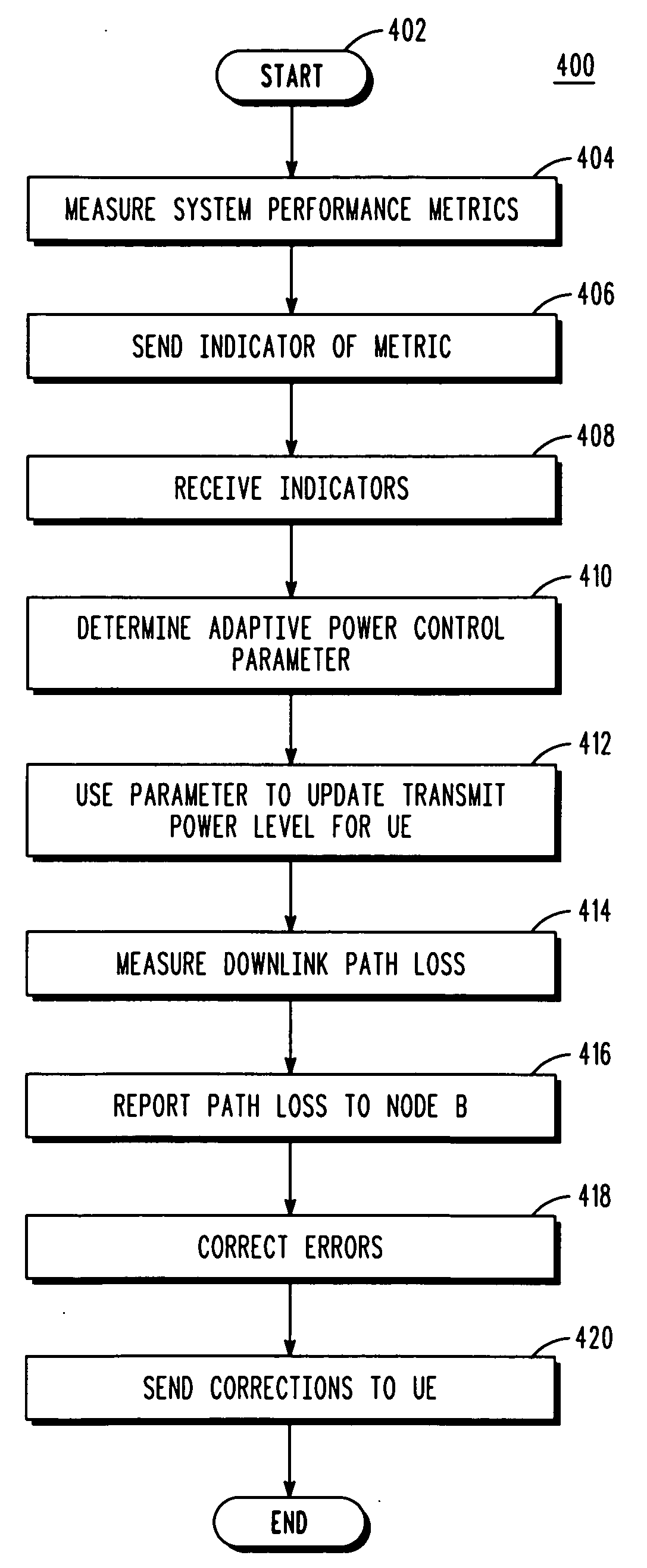
[0032]The above steps 406, 408, 410 can be performed in either or both of the Node Bs and gateway. In a first embodiment, the sending step 406 includes sending the indicator for the at least one system performance metric measurement from the Node B via a backhaul through an edge gateway, and the receiving step 408 includes receiving the indicator forwarded by the edge gateway by the at least one other neighboring Node B, wherein the determining step 410 is performed by the at least one other neighboring Node B. In this embodiment, the adaptive power control parameter is solely determined by the Node Bs (i.e. dumb eGW).

second embodiment

[0033]In a second embodiment, the measuring step 404 includes measuring at least one system performance metric by a plurality of Node Bs, the sending step 406 includes sending an indicator for the at least one system performance metric measurement by the plurality of Node Bs, the receiving step 408 includes receiving the indicators by the edge gateway, wherein the edge gateway adapts the power control parameters for the Node Bs and forwards the updates to the Node Bs, such that the determining step 410 is performed by the edge gateway. In this embodiment, the adaptive power control parameter is solely determined by the edge gateway (i.e. intelligent eGW).

third embodiment

[0034]In a third embodiment, the measuring step 404 includes measuring at least one system performance metric by a plurality of Node Bs, the sending step 406 includes sending an indicator for the at least one system performance metric measurement by the plurality of Node Bs, the receiving step 408 includes receiving the indicators by the edge gateway, wherein the edge gateway pre-processes the indicators for the Node Bs and forwards the pre-processed information to the Node Bs, such that the determining step 410 is performed by both the edge gateway and the plurality of Node Bs. In this embodiment, the adaptive power control parameter is determined between the gateway and Node Bs (i.e. less intelligent eGW).

[0035]In particular, in the third embodiment, the edge gateway pre-processes the messages from the neighboring Node Bs of the serving Node B and generates an indicator by comparing the number of Node Bs sending a particular indicator value against a threshold, wherein if the numb...


PUM


Abstract

A communication system optimizes cell edge performance and spectral efficiency by a first step of measuring, by the Node B, at least one system performance metric. A next step includes sending, by the Node B, an indicator for the at least one system performance metric measurement. A next step includes receiving the indicator for the at least one system performance metric measurement. A next step includes determining an adaptive power control parameter based on the at least one system performance metric measured by the Node B and system performance metrics measured by at the least one other neighboring Node B. A next step includes using the adaptive power control parameter to update an uplink transmit power level for at least one user equipment served by the Node B.

Description

CROSS REFERENCE TO RELATED APPLICATION[0001]This application is related to U.S. patent application Ser. No. 11 / 621,125, attorney docket number CE15524R, filed Jan. 9, 2007, and entitled “Method and Apparatus for Uplink Resource Allocation in a Frequency Division Multiple Access Communication System,” and claims priority from U.S. patent application No. 60 / 815,171, attorney docket number CE16132R, filed Jun. 20, 2006, and entitled “Method and Apparatus for Uplink Power Control in a Frequency Division Multiple Access Communication System.”FIELD OF THE INVENTION[0002]The present invention relates generally to Single Carrier and Multi-Carrier Frequency Division Multiple Access (FDMA) and Orthogonal Frequency Division Multiple Access (OFDMA) communication systems, and, in particular, to uplink power control in Single Carrier and Multi-Carrier FDMA and OFDMA communication systems.BACKGROUND OF THE INVENTION[0003]Single Carrier and Multi-Carrier Frequency Division Multiple Access (FDMA) co...

Claims


Application Information

Patent Timeline
IPC IPC(8): H04Q7/20H04W52/14H04W52/24H04W52/40
CPCH04W52/146H04W52/24H04W52/40H04W52/246H04W52/247H04W52/242H04B7/005H04W52/14H04W88/08
Inventor XIAO, WEMINGHOSH, AMITAVALOVE, ROBERT T.NORY, RAVIKIRANRATASUK, RAPEEPATSUN, YAKUN
Owner MOTOROLA MOBILITY LLC
Why Eureka
Try Eureka