Running control apparatus and running control method for vehicle

a running control and running control technology, applied in the direction of process and machine control, braking systems, instruments, etc., to achieve the effect of suppressing a sudden rise or a sudden fall

Active Publication Date: 2008-08-07
TOYOTA JIDOSHA KK +1
View PDF17 Cites 21 Cited by
  • Summary
  • Abstract
  • Description
  • Claims
  • Application Information

AI Technical Summary

Benefits of technology

[0010]The invention provides an automatic running control apparatus that serves to make an actual vehicle speed coincident with a target vehicle speed or maintain the actual vehicle speed at the target vehicle speed, is configured on the assumption that the control performed by the automatic running control apparatus may not be reflected due to the actuation of an additional control apparatus, and is designed to curb an inconvenience resulting from an increase in (an absolute value of) an integrated value of a difference between a target vehicle speed and an actual vehicle speed during the actuation of the additional control apparatus. More specifically, the invention provides an automatic running control apparatus so configured as to suppress a sudden rise or a sudden fall in a driving force or a driving torque that is generated in a driving system of a vehicle upon the establishment of a state where the control by the automatic running control apparatus is reflected after interruptive actuation of an additional control apparatus.
[0014]It is appropriate for the limitation of the increase or the decrease in the required driving force or the required driving torque in the period in which the target vehicle speed according to running control in this aspect of the invention cannot be achieved to be carried out, as one aspect of implementation, such that the required driving force or the required driving torque is limited to prevent the difference between the actual driving force or the actual driving torque that is actually generated in the driving system and the required driving force or the required driving torque from deviating from “a predetermined limit range”. According to this configuration, even when a situation in which the integrated value of the difference between the target vehicle speed and the actual vehicle speed can increase occurs after continuation of the period in which the target vehicle speed cannot be achieved, the value of the required driving force or the required driving torque is adjusted such that the difference between the required driving force or the required driving torque and the actual driving force or the actual driving torque is confined within the predetermined limit range. Then, the actual driving force or the actual driving torque is restrained from suddenly varying upon reestablishment of the state where the target vehicle speed can be achieved, namely, upon establishment of the state where the required driving force or the required driving torque is reflected in the driving system.
[0019]The first aspect of the invention curbs an inconvenience resulting from a phenomenon in which the control of the driving force or the driving torque for the driving system by the running control apparatus is temporarily suspended due to the intervention of the additional control during the actuation of the apparatus. Especially, owing to a progress made in the art of vehicle running control in recent years, in more cases than ever, a plurality of kinds of control are simultaneously performed in a single vehicle. In the case where the plurality of such kinds of control are simultaneously performed, the first aspect of the invention allows these kinds of control to function compatibly with one another, and is very useful in a vehicle endowed with a variety of control functions.
[0020]In the foregoing aspect of the invention, it should be noted that, as described already, the running control apparatus is configured such that the required driving force or the required driving torque is allowed to shift from the actual driving force or the actual driving torque within the predetermined limit range having the width substantially unequal to 0 even in the case of the establishment of the state where the requirement made by the apparatus of the invention is not reflected in the driving system. According to this configuration, at the time when vehicle speed control is resumed in response to the reestablishment of the state where the requirement made by the apparatus of this aspect of the invention is reflected in the driving system, the required driving force or the required driving torque is offset from the actual driving force or the actual driving torque at that time in a direction reflecting the tendency of changes in the difference between the target vehicle speed and the actual vehicle speed (close to the required driving force or the required driving torque that is given on the basis of the integrated value of the difference between the target vehicle speed and the actual vehicle speed). Thus, good follow-up performance of the actual vehicle speed to the target vehicle speed is ensured after the resumption of vehicle speed control. Furthermore, according to this configuration, even in the case where the actual driving force or the actual driving torque does not coincide with the required driving force or the required driving torque due to changes in the condition of a road surface, an environment in which the vehicle is used, an aged deterioration thereof, or the like in the driving system of the vehicle, good vehicle speed control can be resumed. Therefore, an advantage is gained. In the case where a command value for the required driving force or the required driving torque cannot be accurately or appropriately generated in the driving system, especially where the generated driving force or the generated driving torque is smaller than a required value thereof, if vehicle speed control according to this aspect of the invention is resumed with the required driving force or the required driving torque coincident with the actual driving force or the actual driving torque, the follow-up performance of the actual vehicle speed to the target vehicle speed deteriorates after the resumption of vehicle speed control. However, according to the aforementioned configuration, the required driving force or the required driving torque is offset from the actual driving force or the actual driving torque in the direction reflecting the tendency of the changes in the difference between the target vehicle speed and the actual vehicle speed. Therefore, the actual vehicle speed can be more swiftly made close to the target vehicle speed.

Problems solved by technology

In this running control apparatus, the required driving output deciding unit imposes a limit on an increase or a decrease in the required driving force or the required driving torque when the determination unit determines that the required driving force or the required driving torque is unrealizable in the control of the driving system.
Such control constitutes a factor in disturbances of the behavior of the vehicle or the occurrence of a sudden rise or a stagnation in vehicle speed.

Method used


Image

  • Running control apparatus and running control method for vehicle
  • Running control apparatus and running control method for vehicle
  • Running control apparatus and running control method for vehicle

Examples


Embodiment Construction

[0028]The invention will be described hereinafter in detail with reference to the accompanying drawings as to an embodiment thereof. In the drawings, like reference symbols represent like parts.

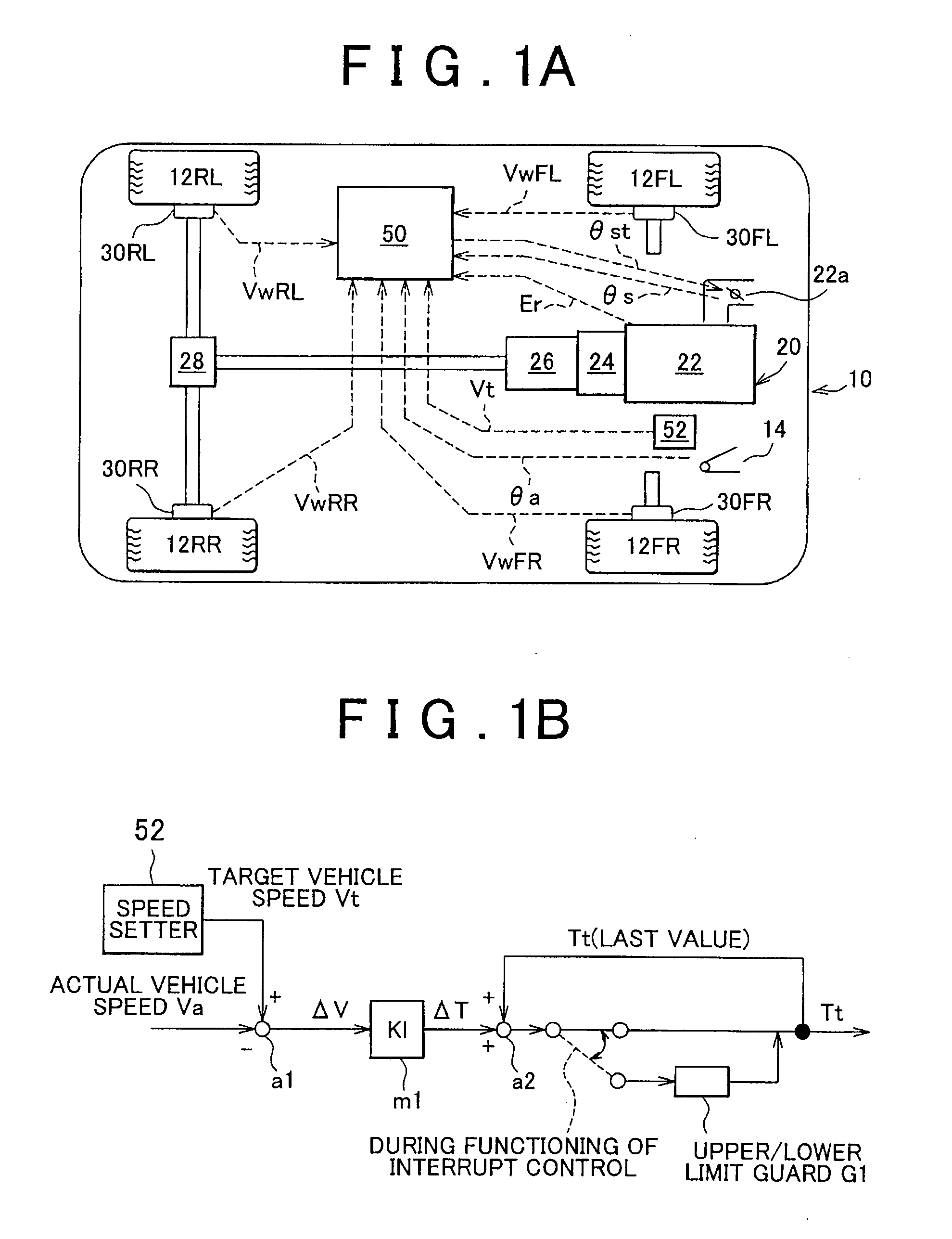
[0029](Configuration of Apparatus) FIG. 1A schematically shows an automobile mounted with a running control apparatus according to the embodiment of the invention. In FIG. 1A, a vehicle 10 having a front-left wheel 12FL, a front-right wheel 12FR, a rear-left wheel 12RL, and a rear-right wheel 12RR is mounted with a driving system 20 for generating a driving force for each of the wheels (only the rear wheels in an example illustrated in FIG. 1A because the vehicle 10 is a rear-wheel-drive vehicle) in accordance with depression of an accelerator pedal 14 by a driver in a normal mode. In the illustrated example, the driving system 20 is designed such that a driving torque or a rotational driving force that is output from an engine 22 via a torque converter 24, an automatic transmission 26, a dif...


PUM


Abstract

A running control apparatus for a vehicle includes a required driving output deciding unit that decides a required driving force of a driving system of the vehicle on the basis of an integrated value of a difference between a target vehicle speed and an actual vehicle speed, a driving control unit that controls the actuation of the driving system on the basis of the required driving force, and a determination unit that determines whether or not the required driving force is unrealizable in the control of the driving system due to the intervention of additional control. The required driving output deciding unit imposes a limit on an increase or a decrease in the required driving force when the determination unit determines that the required driving force is unrealizable in the control of the driving system.

Description

INCORPORATION BY REFERENCE[0001]The disclosure of Japanese Patent Application No. 2007-022790 filed on Feb. 1, 2007 including the specification, drawings and abstract is incorporated herein by reference in its entirety.BACKGROUND OF THE INVENTION[0002]1. Field of the Invention[0003]The invention relates to a running control apparatus and a running control method for a vehicle such as an automobile or the like. More specifically, the invention relates to a running control apparatus and a running control method for a vehicle that control a driving force of the vehicle or a driving torque of a driving system (an engine, a motor, or the like) such that a vehicle speed of the vehicle coincides with a target vehicle speed.[0004]2. Description of the, Related Art[0005]In recent years, vehicles such as automobiles and the like have been mounted with “automatic running control apparatuses” for automatically controlling vehicle speed through, for example, “cruise control”, “creep running cont...

Claims


Application Information

Patent Timeline
Patent Type & Authority Applications(United States)
IPC IPC(8): B60W30/14B60W40/10B60K31/00F02D29/02
CPCB60K31/047B60W2710/105B60W2550/142B60W2552/15
Inventor INOUE, GENISHIDA, YASUHITO
Owner TOYOTA JIDOSHA KK
Why Eureka
Try Eureka