Adaptive antenna reception method and device

a technology of antenna reception and receiver, applied in direction finders using radio waves, instruments, multiplex communication, etc., can solve problems such as interference with other signals, and achieve the effects of preventing stepping out, simple construction and operation, and improving the follow-up performance of directional beams

Inactive Publication Date: 2009-07-21
NEC CORP
View PDF19 Cites 2 Cited by
  • Summary
  • Abstract
  • Description
  • Claims
  • Application Information

AI Technical Summary

Benefits of technology

[0057]As is described above, in accordance with the present invention, the transmission channel estimation means corrects a transmission channel. The antenna weight adaptive update means adaptively controls the antenna weight using signals received by the respective antenna elements, and the antenna weight direction constraint means corrects the antenna weight. In other words, the transmission channel correction is performed independently of the antenna weight control. Consequently, the antenna weight does not contain the components of the transmission channel correction, and is adaptively controlled by phase correction depending only on signal arrival direction. Thereby, the antenna weight direction constraint means can correct the antenna weight in such a manner as to maintain the beam gain constant in the arrival direction of a desired signal. Thus, the gain of the desired signal component of beam output remains constant, resulting in an improvement in the follow-up performance of a directional beam. In addition, step out can be prevented.
[0058]Besides, the antenna weight direction constraint means corrects the antenna weight based on a direction vector to maintain the beam gain constant in the arrival direction of a desired signal. Therefore, the gain of the desired signal component of beam output remains constant.
[0059]In addition, the antenna correlation averaging means averages the correlations between the respective adjacent antenna elements obtained by the adjacent antenna correlation detection means. The arctangent calculation means and the direction vector calculation means obtains a direction vector based on the average value. Thus, the direction vector of a desired signal can be obtained based on the correlation between the adjacent antenna elements with simple construction and operation.

Problems solved by technology

In the CDMA system, however, has a problem in that, when a base station receives a desired signal from a particular user, interference occurs with other signals from users who access the same base station simultaneously with the particular user.

Method used


Image

  • Adaptive antenna reception method and device
  • Adaptive antenna reception method and device
  • Adaptive antenna reception method and device

Examples


Embodiment Construction

[0060]Referring now to the drawings, a description of a preferred embodiment of the present invention will be given in detail.

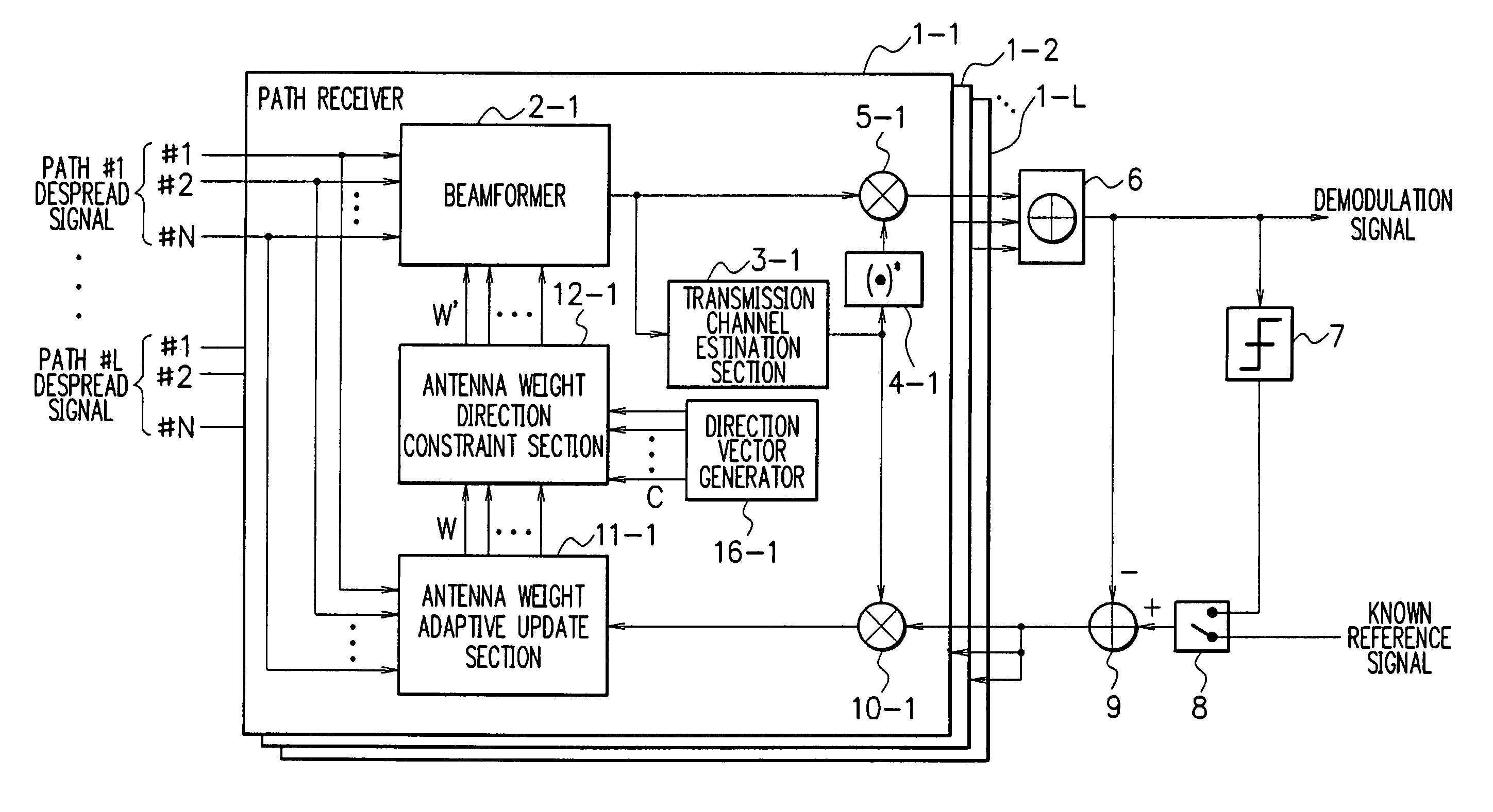
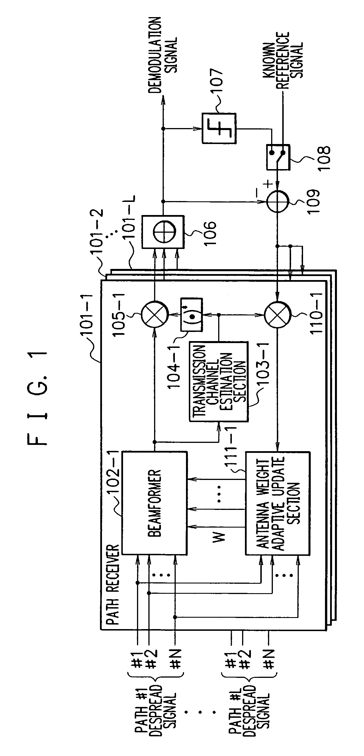
[0061]FIG. 4 is a block diagram showing the construction of an adaptive antenna receiver according to an embodiment of the present invention. Referring to FIG. 4, the adaptive antenna receiver comprises path receivers 1-1 to 1-L, a combiner 6, a determination unit 7, a switch 8, and a subtractor 9.

[0062]There are provided L pieces of the path receivers 1-1 to 1-L to perform multipath combining correspondingly to multipath propagation channels in a mobile communication environment. All of the path receivers 1-1 to 1-L have the same construction.

[0063]The path receivers 1-1 includes a beamformer 2-1, a transmission channel estimation section 3-1, a complex conjugate operation section 4-1, multipliers 5-1 and 10-1, an antenna weight adaptive update section 11-1, an antenna weight direction constraint section 12-1, and a direction vector generator 16-1.

[0064]The ...


PUM


Abstract

An adaptive antenna receiver whose follow-up performance is improved with respect to the angle change of the arrival direction of a desired signal. An antenna weight adaptive update section (11-1) adaptively updates the antenna weight according to a signals received by each antenna element and an error signal obtained from a desired signal corrected based on transmission channel estimation. An antenna weight direction constraint section (12-1) performs the constraint process for the antenna weight obtained by the antenna weight adaptive update section (11-1) to maintain the beam gain constant in the arrival direction of the desired signal. A beamformer (2-1) receives the desired signal through an array antenna using the antenna weight which has undergone the constraint process performed by the antenna weight direction constraint section (12-1). A transmission channel estimation section (3-1) estimates the transmission channel of the desired signal received by the beamformer (2-1) to correct the desired signal based on the estimation result.

Description

TECHNICAL FIELD[0001]The present invention relates to an adaptive antenna receiver, and more particularly, to an adaptive antenna receiver for adaptively forming am antenna directivity or directional beam in a CDMA system to receive a desired signal from a particular user while suppressing interference signals from other users.BACKGROUND ART[0002]The CDMA (Code Division Multiple Access) system has the potential of increasing the subscriber capacity with respect to the radio frequency and attracts attention as a radio access system for a mobile communication cellular system.[0003]In the CDMA system, however, has a problem in that, when a base station receives a desired signal from a particular user, interference occurs with other signals from users who access the same base station simultaneously with the particular user. To eliminate such interference signals to properly receive a desired signal, an array antenna is usable.[0004]An array antenna comprises a plurality of antenna eleme...

Claims


Application Information

Patent Timeline
Patent Type & Authority Patents(United States)
IPC IPC(8): H04M1/00H01Q3/26H04B1/707H04B7/08H04J99/00
CPCH04B7/0854H01Q3/2605
Inventor YOSHIDA, SHOUSEI
Owner NEC CORP
Why Eureka
Try Eureka