Depilating device

a depilating device and a technology for hair removal, applied in the field of depilating devices, can solve the problems of deteriorating the user-friendliness of the depilating device, difficult to discriminate whether unremoved hair remains, and takes a lot of trouble, so as to eliminate the stimulus, remove flocks easily, and follow-up the effect of the wiper

Inactive Publication Date: 2007-10-04
MATSUSHITA ELECTRIC WORKS LTD
View PDF8 Cites 3 Cited by
  • Summary
  • Abstract
  • Description
  • Claims
  • Application Information

AI Technical Summary

Benefits of technology

[0013]It is further preferable that the wiper is floatable on the skin surface. In this case, the floatable wiper makes it possible to eliminate the stimulus on the skin, and the follow-up performance of the wiper even with respect to such a convex part as a bony part of the skin surface can be improved.
[0014]It is also preferable that the wiper is provided on one of a front side and a back side of the main body casing. In this case, by arranging the front side (or back side) of the main body casing, on which side the wiper is provided, in rear of the depilation head while a front surface and a back surface of the main body casing are being gripped by user's fingers, the wiper can ensure wiping off the bubbles adhering to the skin surface after depilating using the depilation head.
[0015]Furthermore, it is preferable that the wiper and the head frame are detachable from the main body casing. In this case, by detaching the wiper as well as the head frame from the main body casing, it is possible to easily remove flocks adhering to the wiper and the head frame or those entering into the depilation head, thus facilitating cleaning operation.
[0016]Moreover, it is preferable that the wiper is detachable from the head frame. In this case, if dry depilation is made in a dry state where soap is not used, the wiper can be detached from the head frame. This can facilitate switching depilation operation between depilation using soap and dry depilation and thereby improving the user-friendliness of the depilating device. This can also facilitate replacement operation when the wiper deteriorates.
[0017]Further, it is preferable that the wiper is height-adjustable with respect to the head frame in a direction almost perpendicular to the skin surface. In this case, the height of the wiper can be switched with respect to a direction almost perpendicular to the skin surface. Therefore, if the depilation is made using soap, the wiper is lifted and held at a position at which the wiper touches the skin surface. At this time, by vertically adjusting the wiper, it is possible to easily adjust pressing load of the wiper on the skin surface, whereby the stimulus can be made weaker. Besides, it is possible to remove hair while stretching the skin using the wiper by the appropriate pressing load of the wiper on the skin surface. On the other hand, if the depilating device is used without soap, the wiper can be lowered and held at a position at which the wiper does not touch the skin. It is, therefore, possible to easily deal with dry depilation.
[0018]Furthermore, it is preferable that the wiper is made of elastomer. In this case, it is possible to eliminate stimulus on the skin by using the elastomer wiper and prevent damage on the skin surface. Besides, it is possible to sufficiently improve the follow-up performance of the wiper even with respect to such a convex part as a bony part of the skin surface.

Problems solved by technology

This makes it difficult to discriminate whether unremoved hairs remain.
Due to this, a user is forced to wipe off the bubbles by himself or herself whenever the skin surface becomes invisible, which takes lots of trouble and deteriorates user-friendliness of the depilating device.

Method used


Image

  • Depilating device
  • Depilating device
  • Depilating device

Examples


Embodiment Construction

[0029]Embodiments of the present invention will be explained below with reference to the accompanying drawings.

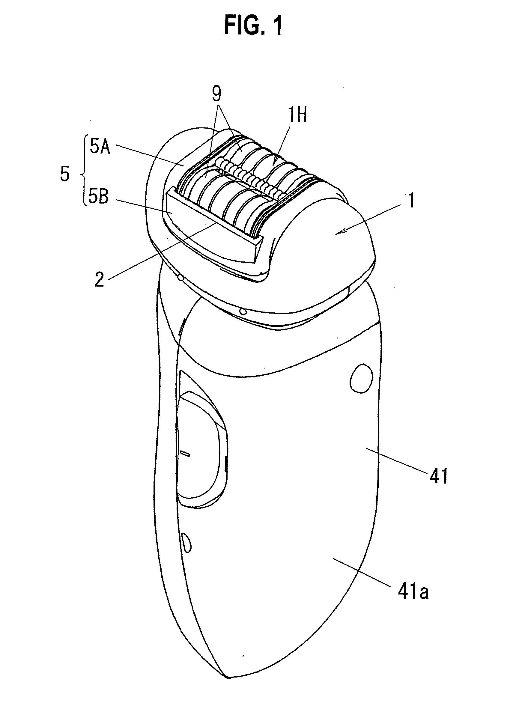
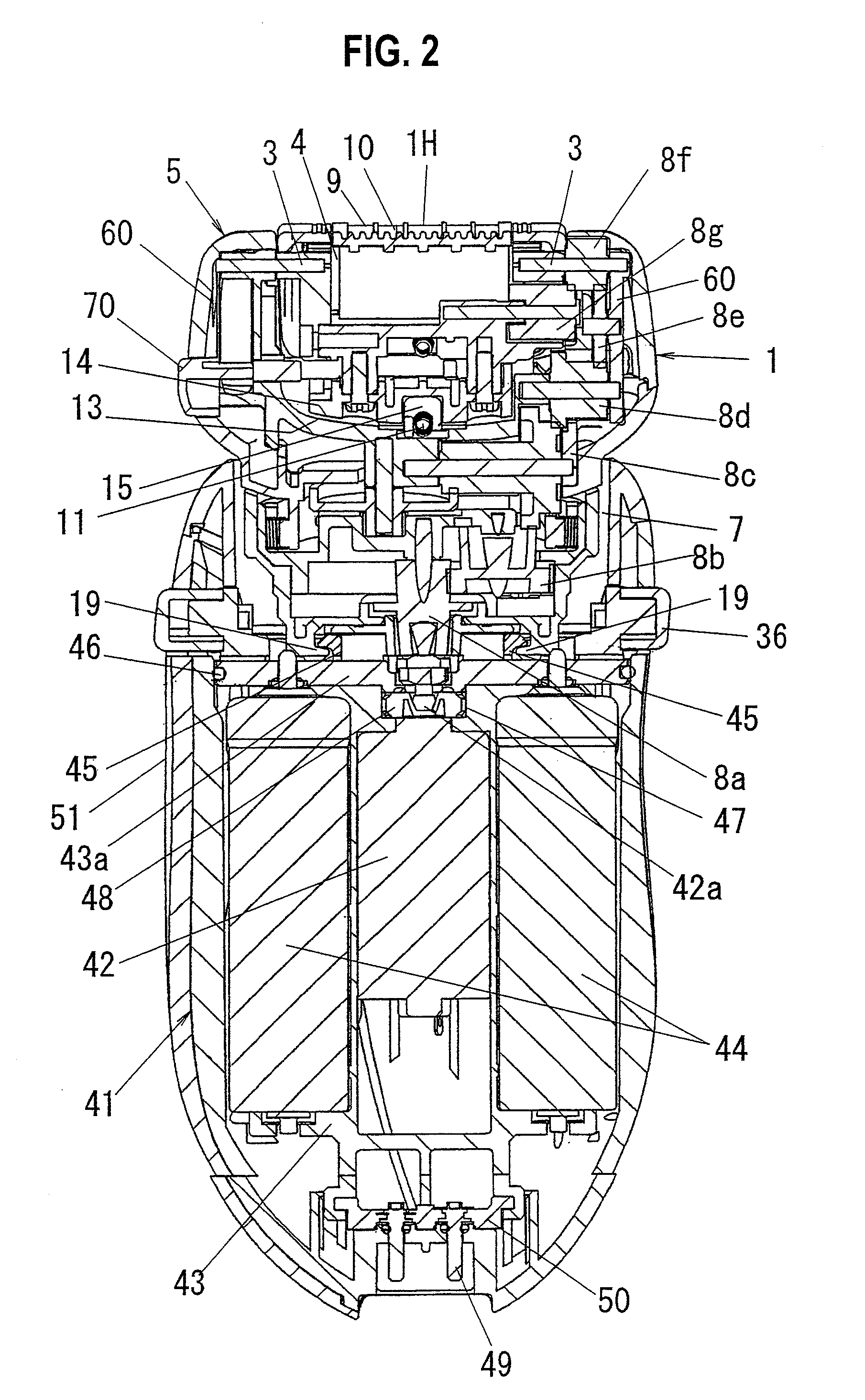
[0030]A depilating device according to a first embodiment of the present invention is a depilating device employed to remove hair from the body of a user for cosmetic purposes. As shown in FIGS. 1 and 2, the depilating device includes a main body casing 41 that includes a grip 41a which the user can grip by the hand and that includes therein a motor (driving unit) 42, and a depilating unit 1 that includes a depilation head 1H and that is detachably provided on the main body casing 41. The depilation head 1H includes rotary cylinders 4 and a depilating portion 9 having a plurality of depilating claws (e.g., a movable claw and a fixed claw) driven to be opened or closed by the rotary cylinders 4 and holding the hair between the depilating claws. The depilation head 1H is configured so that the hair is put between the depilating claws to remove the hair according to axial rota...


PUM


Abstract

In a depilating device for making depilation using a soap in which a depilation head including a depilating portion for removing hair is attached to a main body casing including a manually grippable grip and having a waterproof structure, a wiper for wiping off bubbles adhering to a skin surface after depilating is provided on a head frame that surrounds the depilating portion.

Description

CROSS REFERENCE TO RELATED APPLICATION[0001]This application is based upon and claims the benefit of priority from prior Japanese Patent Application P2006-089576, filed on Mar. 28, 2006; the entire contents of which are incorporated by reference herein.BACKGROUND OF THE INVENTION[0002]1. Field of the Invention[0003]The present invention relates to a depilating device capable of removing hair using soap.[0004]2. Description of the Related Art[0005]Conventionally, there has been proposed a depilating device configured so that a depilating unit is attached to a main body casing including a driving source. As a depilating device of this type, there has been known a depilating device in which a depilating unit includes a rotary cylinder rotated by a driving source and a depilation head having a plurality of depilating claws driven to be opened / closed by rotation of the rotary cylinder and used to catch and remove hair (for example, see Japanese Patent Application Laid-open No. 2001-14913...

Claims


Application Information

Patent Timeline
Patent Type & Authority Applications(United States)
IPC IPC(8): A61B17/50
CPCA45D26/0038A45D26/0028B26B19/38B26B19/40
Inventor SUEYOSHI, HIDEKAZUWANG, WEIHASHIGUCHI, TETSURONISHIMURA, SHINJI
Owner MATSUSHITA ELECTRIC WORKS LTD
Why Eureka
Try Eureka