
Charge control device for batteries

a technology for controlling devices and batteries, which is applied in the direction of circuit monitoring/indication, instruments, transportation and packaging, etc., can solve the problems of increasing cost and difficulty in properly controlling the charge of batteries to be installed in various motor vehicles, and achieve the effect of increasing the scale and/or cost of the charge control devi

Active Publication Date: 2008-08-14
DENSO CORP
View PDF6 Cites 13 Cited by
  • Summary
  • Abstract
  • Description
  • Claims
  • Application Information

AI Technical Summary

Benefits of technology

[0011]In view of the background, an object of at least one aspect of the present invention is to provide charge control devices, which are capable of rewriting data installed beforehand therein and required to control charge of a battery installed in a vehicle without increasing the charge control devices in scale and / or cost.

Problems solved by technology

The variation in the SOC of a battery makes it difficult to properly control the charge of batteries to be installable in various motor vehicles on the basis of common programs and data required to execute the battery-charge control.
These additional components required for the engine control system to communicate with the memory writer may increase the scale of the engine control system, resulting an increase in cost thereof.

Method used


Image

  • Charge control device for batteries
  • Charge control device for batteries
  • Charge control device for batteries

Examples


Embodiment Construction

[0027]An embodiment of the present invention will be described hereinafter with reference to the accompanying drawings.

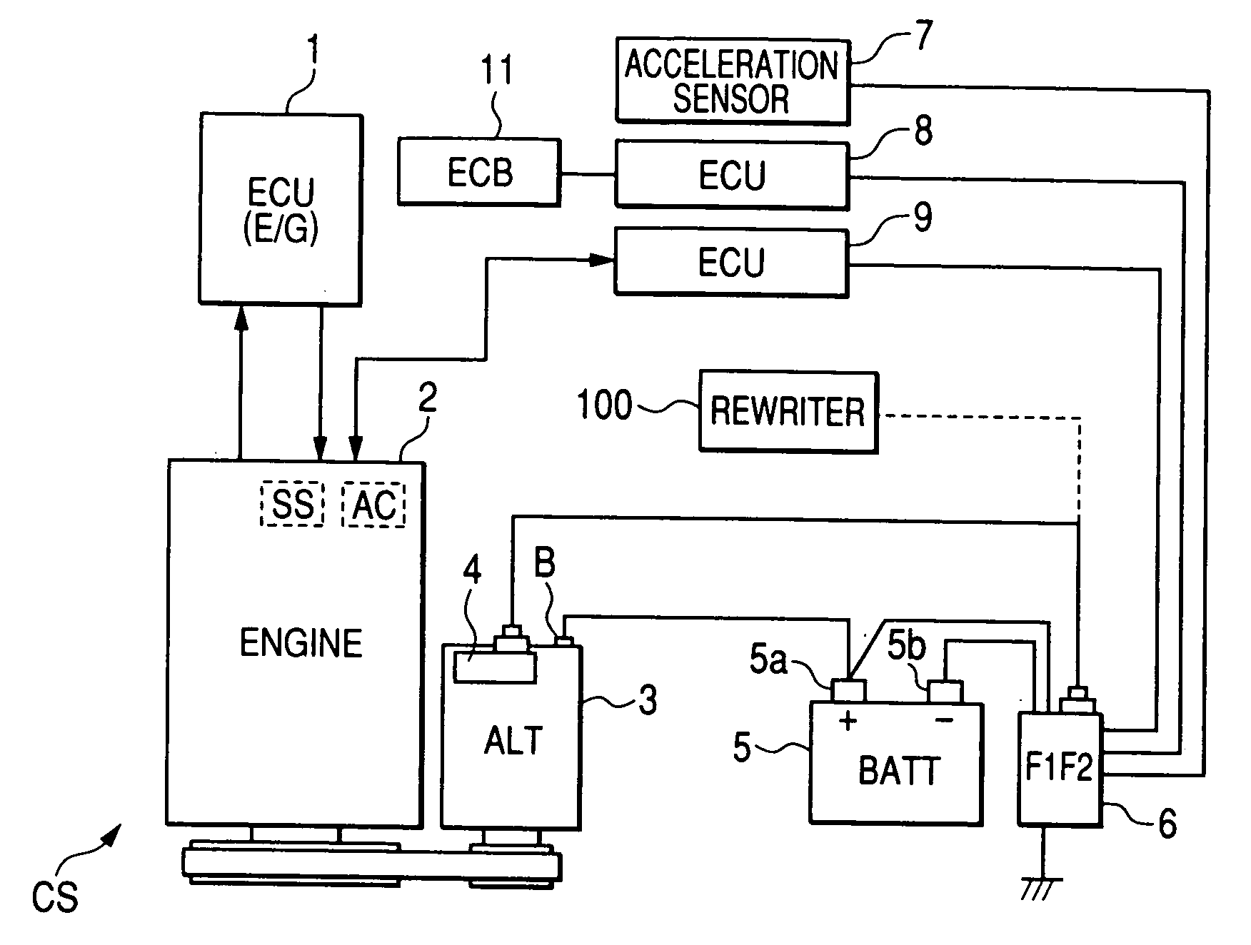
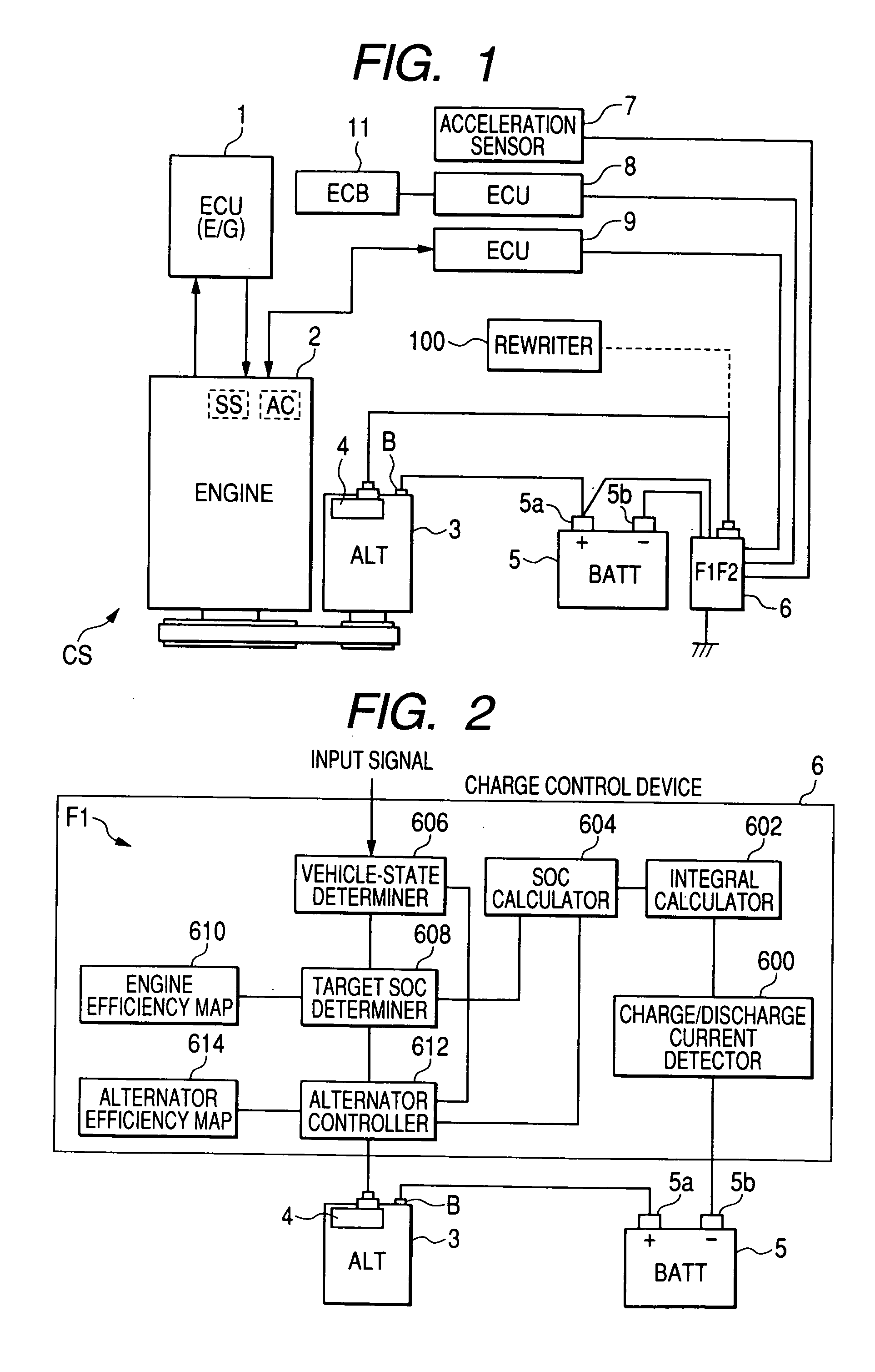
[0028]Referring to FIG. 1, there is provided a charging system CS installed in a motor vehicle (referred to simply as “vehicle”) and equipped with a charge control device (CC) 6 according to the embodiment of the present invention. To the charge control system 6, a predetermined ID is allocated.

[0029]The charging system CS includes an electronic control unit ECU 1 for controlling an engine 2 of the vehicle, an alternator (ALT) 3 as an example of power-generators, a battery (BATT) 5, and the charge control device 6. The charging system CS also includes an acceleration sensor 7, a brake ECU (ECB) 8, and a fuel control ECU 9. A rewriter 100 illustrated in FIG. 1 is an example of external devices. To the rewriter 100, a predetermined ID is allocated.

[0030]The ECU 1 is connected to sensors SS for measuring parameters associated with the operating state of the vehicle, su...


PUM


Abstract

In a charge control device installable in a motor vehicle and designed to execute charge control for a battery based on an output power of a power generator, a nonvolatile memory stores therein data required to execute the charge control for the battery. A communication circuit is communicably connectable to first and second devices different from each other. The first device allows entrance of information required to rewrite the data stored in the nonvolatile memory. A rewriting unit rewrites the data stored in the nonvolatile memory based on the entered information only when the first device is communicably connected to the communication circuit.

Description

CROSS REFERENCE TO RELATED APPLICATIONS[0001]This application is based on Japanese Patent Application No. 2007-033795 filed on Feb. 14, 2007. The descriptions of the Patent Application are all incorporated herein by reference.FIELD OF THE INVENTION[0002]The present invention relates to charge control devices for batteries to be installed in motor vehicles; these systems are capable of controlling charge of a battery. More particularly, the present invention relates to such charge control devices that store data required to control charge of a battery.BACKGROUND OF THE INVENTION[0003]Batteries to be installed in motor vehicles are used as a source of energy in a vehicle when the engine, and hence the alternator is not running. For example, when the engine speed is slow or the engine is not running, the battery works to provide a voltage of the battery to vehicle loads. On the other hand, when the engine is running, the alternator works to supply an output voltage thereof to both the ...

Claims


Application Information

Patent Timeline
Patent Type & Authority Applications(United States)
IPC IPC(8): H02J7/14
CPCH02J7/1461H02J7/14H02J7/0049
Inventor ABE, KUNIHIRO
Owner DENSO CORP
Learn More