Tile marking and/or cutting device

Inactive Publication Date: 2008-08-21
DOZIER EULA C
View PDF13 Cites 2 Cited by
  • Summary
  • Abstract
  • Description
  • Claims
  • Application Information

AI Technical Summary

Benefits of technology

[0005]A preferred way of accomplishing this is with a base that includes a fence that can guide along the edges of laid tiles and the superposed tiles. The base also includes a spring that lightly presses the probe away from the fence to contact and stay engaged with a wall or obstruction as the base moves along, the superposed whole tiles are restrained by the fence from moving toward the wall or obstruction, and a board or straight edge can be laid along the edge of the superposed til

Problems solved by technology

All of these systems mark one tile at a time u

Method used


Image

  • Tile marking and/or cutting device
  • Tile marking and/or cutting device
  • Tile marking and/or cutting device

Examples


Example

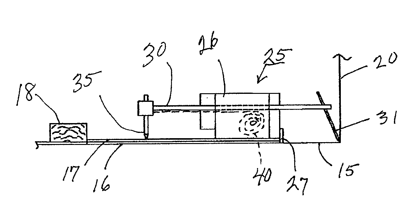
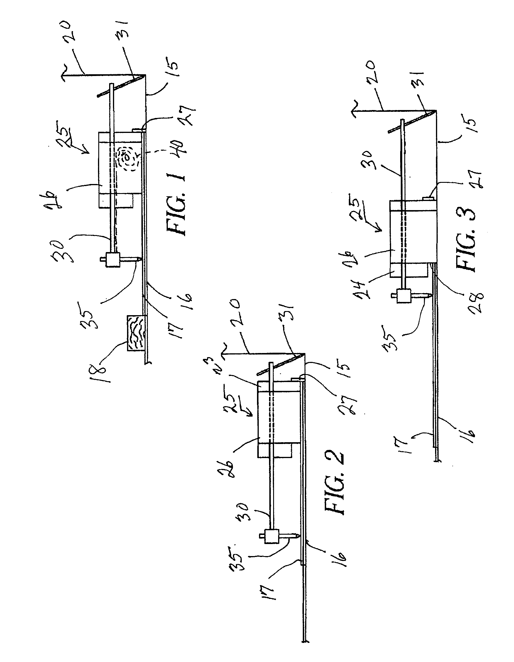
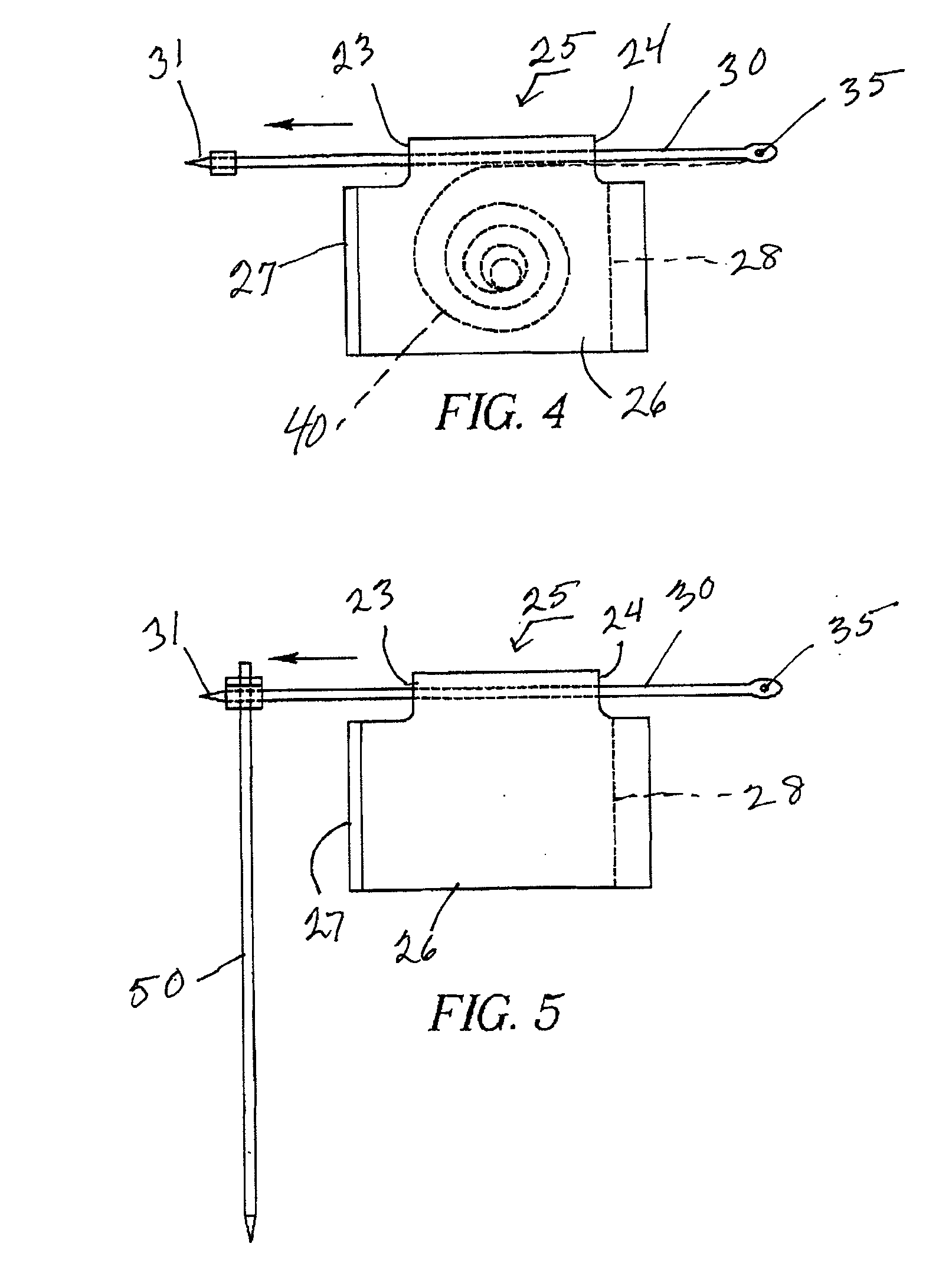
[0014]FIGS. 1-3 schematically show how a simplified preferred embodiment 25 of the inventive marking device can be used for marking different dimensions of gaps between a laid tile 16 on floor 15 and a wall or obstacle 20. Tile 17 to be marked is superposed over laid tile 16, and a fence 27 of base 26 guides along the edges of tiles 16 and 17. This allows base 26 and fence 27 to move along a whole row of laid tiles 16 and superposed tiles 17 while marking a line on or cutting superposed tiles 17. To facilitate movement of the base 26, rolling elements, such as wheels, ball bearings, or the like, can be mounted on the base 26 for engagement with a surface beneath the base 26, such as a laid tile 17.

[0015]Fence 27 keeps tile 17 from moving toward wall 20. This is because fence 27 also guides on laid tile 16 and thus prevents superposed tile 17 from moving past the edge of laid tile 16. A board or straight edge 18 can be positioned against the rear edge of a superposed tile 17, such as...


PUM


Abstract

A tile marking tool uses a probe mounted on a biased marking arm to engage and follow a contour of an obstruction, such as a wall, cabinet, or heat vent, adjacent which floor tile must be installed. As the tool is moved along the wall, a marking element on the other end of the marking arm marks or cuts the contour of the obstruction on a tile or tiles to be laid, facilitating cutting and/or placement of the tile in such a way as to fit well against the obstruction. Embodiments include a corner marking arrangement for marking tiles to be laid in reentrant corners. The corner marking arrangement includes a corner arm attachable to and orthogonal to the marking arm so that the tool is used in usual fashion as it approaches the reentrant corner.

Description

TECHNICAL FIELD[0001]Marking of tiles for cutting.BACKGROUND AND SUMMARY[0002]Floor tiles are generally laid first in open areas of a floor and are then cut to fit gaps that occur along walls or around obstacles. Many tile marking devices have been proposed for marking tiles to be cut to fit into the resulting gaps. These generally measure a gap and then mark the measurement on a tile, proceeding one tile at a time. A manual method positions a whole tile upside down against a wall or obstruction so that the whole tile overlaps a laid tile, and then a mark is made along the laid tile for a portion of the whole tile to be cut away and turned right side up to fit into the gap. All of these systems mark one tile at a time using procedures that are inconvenient and slow.[0003]Embodiments disclosed herein aim at a faster and more efficient way of marking tiles to fit accurately within gaps between laid tiles and walls or obstructions. Embodiments also cut tiles to be laid directly, rather...

Claims


Application Information

Patent Timeline
IPC IPC(8): G01B1/00
CPCB25H7/02E04F21/22E04F21/0076
Inventor DOZIER, EULA C.
Owner DOZIER EULA C
Why Eureka
Try Eureka