Nested variable field dynamoelectric machine

a dynamoelectric machine and variable field technology, applied in the direction of electric propulsion mounting, transportation and packaging, gearing, etc., can solve the problem of cumbersome cross-drive propulsion system

Active Publication Date: 2008-08-21
HAMILTON SUNDSTRAND CORP
View PDF26 Cites 34 Cited by
  • Summary
  • Abstract
  • Description
  • Claims
  • Application Information

AI Technical Summary

Problems solved by technology

However, in order to do so, cross-drive systems typically require the use of a plurality of electric motors.
Thus, c

Method used


Image

  • Nested variable field dynamoelectric machine
  • Nested variable field dynamoelectric machine
  • Nested variable field dynamoelectric machine

Examples


Embodiment Construction

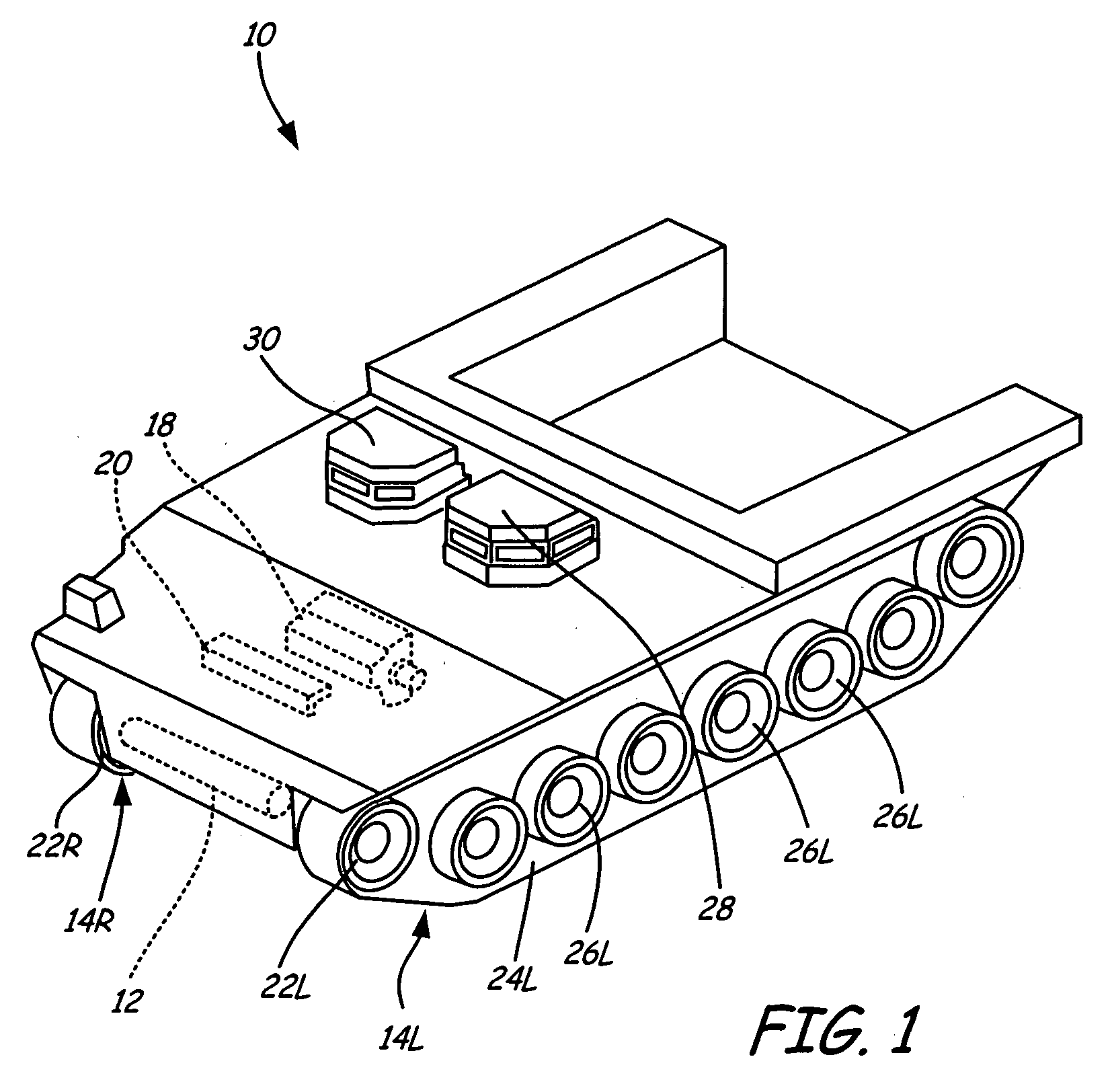
[0008]FIG. 1 shows track-laying vehicle 10 in which cross-drive propulsion system 12 is used. Vehicle 10 comprises a heavy track-laying vehicle such as could be modified for military or construction applications. Vehicle 10 includes cross-drive propulsion system 12, left-side track system 14L, right-side track system 14R, diesel motor 18 and electric generator 20. Cross-drive propulsion system 12 includes variable field permanent magnet motors and, as such, relies on electric power to operate. Diesel engine 18 provides mechanical input to generator 20 for producing the electric power required for operating cross-drive propulsion system 12. Cross-drive propulsion system 12, in turn, drives left-side track system 14L and right-side track system 14R to propel vehicle 10. Left-side track system 14L includes drive sprocket 22L, track 24L and road wheels 26L. Drive sprocket 22L is connected to receive output of propulsion system 12. Sprocket 22L rotates to pull track 24L such that vehicle...


PUM


Abstract

A dynamoelectric machine comprises a first rotor shaft, a second rotor shaft and a central element. The first rotor shaft rotates about a central axis of the machine and has a first magnetic drive element disposed about an outer circumference of the first rotor shaft. The second rotor shaft rotates about the first rotor shaft and has a second magnetic drive element disposed about an inner circumference of the second rotor shaft. The central element is disposed between the first rotor shaft and the second rotor shaft and is configurable to remain stationary while the first rotor shaft and the second rotor shaft rotate about the central axis. The central element also includes a third magnetic drive element for interacting with the first magnetic drive element, and a fourth magnetic drive element for interacting with the second magnetic drive element.

Description

BACKGROUND OF THE INVENTION[0001]This invention relates generally to dynamoelectric machines and more particularly to drive systems involving multiple integrated brushless permanent magnet (PM) motors. PM motors convert electrical energy to kinetic energy by exploiting the electromagnetic relationship between a magnet and an electric field. Conversely, PM generators convert kinetic energy to electrical energy using the inverse of the electromagnetic relationship. PM motors and PM generators are collectively referred to as dynamoelectric machines. In a typical PM motor, electric current is passed through stationary windings of conductive wires to generate an alternating magnetic field to push and / or pull a magnetic rotor. The magnetic rotor is coupled to a shaft to produce rotational shaft power. Additionally, high output torque can be obtained from PM motors at low rotor speeds. For these reasons and others, PM motors are well suited for propulsion systems for large, track-laying ve...

Claims


Application Information

Patent Timeline
IPC IPC(8): H02K7/10
CPCB60K1/02Y02T10/6286B60K6/365B60K6/46B60K6/547B60K17/046B60K17/145B60W10/06B60W10/08B60W10/115B60W20/00B60Y2200/25H02K7/116H02K16/02H02K21/024Y02T10/6217B60K6/26Y02T10/62B60W2510/08B60W2050/001
Inventor HIMMELMANN, RICHARD A.SHAHAMAT, MOHAMMAD
Owner HAMILTON SUNDSTRAND CORP
Why Eureka
Try Eureka