Ink cartridges and systems having such ink cartridges

a technology of ink cartridges and systems, applied in the field of ink cartridges, can solve the problems of user's hands being dirtied with ink, mounting portion becomes dirtied, and new ink cartridges may also become dirtied

Inactive Publication Date: 2008-08-21
BROTHER KOGYO KK
View PDF17 Cites 28 Cited by
  • Summary
  • Abstract
  • Description
  • Claims
  • Application Information

AI Technical Summary

Benefits of technology

[0009]Therefore, a need has arisen for ink cartridges which overcome these and other shortcomings of the related art. A technical advantage of the present invention is that the ink cartridge may prevent ink from dripping from the ink cartridge or reduce an amount of ink which drips from the ink cartridge. Another technical advantage of the present invention is that the ink cartridge readily may be removed from the recording apparatus.
[0010]According to an embodiment of the present invention, an ink cartridge comprises a case, an ink supply portion, an air intake portion, and at least one resilient member. The case comprises a front face and a rear face opposite the front face. The case has at least a portion of an ink chamber defined therein, and the ink chamber is configured to store ink therein. The ink supply portion is positioned at the front face of the case. The ink supply portion is configured to dispense ink from an interior of the ink chamber to an exterior of the ink chamber, and the air intake portion is positioned at the case. The air intake portion is configured to draw air into the ink chamber. The at least one resilient member has a first portion positioned at the front face of the case, and a second portion which is positioned a predetermined distance away from the front face of the case in a predetermined direction away from the ink chamber. The resilient member extends from the front face of the case further than the ink supply portion in the predetermined direction.
[0011]According to another embodiment of the present invention, an ink cartridge comprises a case, an ink supply portion, an air intake portion, and at least one resilient member. The case comprises a front face and a rear face opposite the front face. The case has at least a portion of an ink chamber defined therein, and the ink chamber is configured to store ink therein. The ink supply portion is positioned at the front face of the case. The ink supply portion is configured to dispense ink from an interior of the ink chamber to an exterior of the ink chamber, and the air intake portion is positioned at the case. The air intake portion is configured to draw air into the ink chamber. The at least one resilient member has a first portion positioned at the front face of the case, and a second portion which is positioned a predetermined distance away from the front face of the case in a predetermined direction away from the ink chamber. The resilient member extends from the front face of the case further than the ink supply portion in the predetermined direction. The first portion of the at least one resilient member is unaligned with each of the ink supply portion and the air intake portion in the predetermined direction.
[0012]According to yet another embodiment of the present invention, a system comprises an ink cartridge and an inkjet printer. The ink cartridge comprises a case, an ink supply portion, a first conductive coil, and a second conductive coil spring. The case comprises a front face and a rear face opposite the front face. The case has at least a portion of an ink chamber defined therein, and the ink chamber is configured to store ink therein. The ink supply portion is positioned at the front face of the case. The ink supply portion is configured to dispense ink from an interior of the ink chamber to an exterior of the ink chamber. The first conductive coil spring has a first portion positioned at the front face of the case, and a second portion which is positioned a predetermined distance away from the front face of the case in a predetermined direction. The first conductive coil spring is configured to be electrically connected to ink in the ink chamber. The second conductive coil spring has a first portion positioned at the front face of the case, and a second portion which is positioned a predetermined distance away from the front face of the case in the predetermined direction. The second conductive coil spring is configured to be electrically connected to ink in the ink chamber. The inkjet printer comprises a first electric terminal, a second electric terminal, and a determining portion. The first electric terminal is configured to contact the first conductive coil spring. The second electric terminal is configured to contact the second conductive coil spring. The determining portion is configured to determine an amount of ink disposed in the ink chamber based on an electric resistance between the first electric terminal and the second electric terminal.
[0013]Other features and technical advantages of the present invention will be apparent to persons of ordinary skill in the art in view of the following

Problems solved by technology

When the ink drips onto the mounting portion, the mounting portion becomes dirtied.
After the mounting portion is dirtied, when a new ink cartridge is mounted to the mounting portion, the new ink cartridge also may become dirtied.
When the new ink cartridge is removed from the mounting portion, a hand of user also may become dirtied with ink.

Method used


Image

  • Ink cartridges and systems having such ink cartridges
  • Ink cartridges and systems having such ink cartridges
  • Ink cartridges and systems having such ink cartridges

Examples


case 20

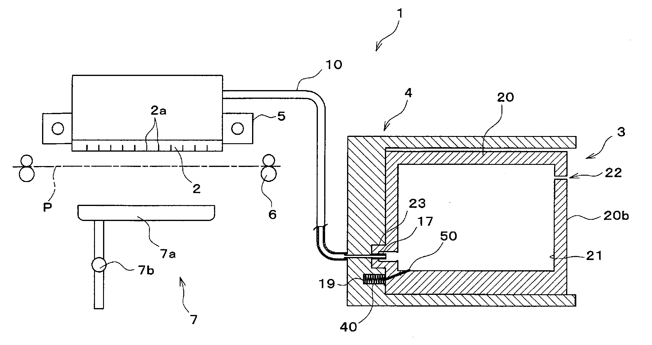
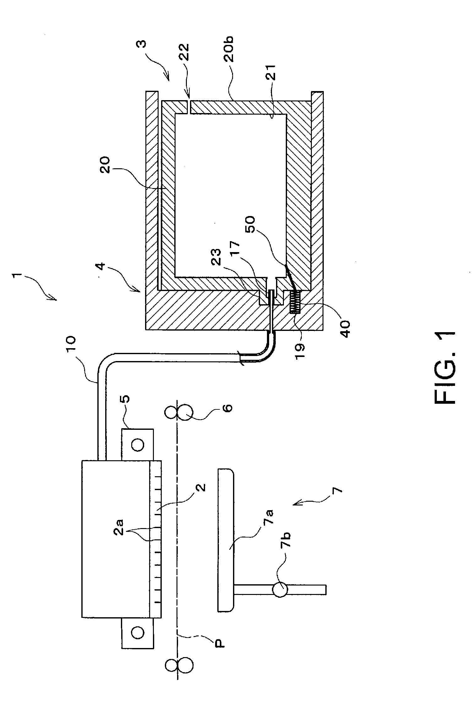
[0041]Case 20 may have a substantially rectangular parallelepiped shape having front face 20a, a rear face 20b opposite front face 20a, a top face, a bottom face opposite the top face, a right side face, and a left side face opposite the right side face. Each of the top face and the bottom face is connected to front face 20a and rear face 20b, and each of the right side face and the left side face is connected to front face 20, rear face 20b, the top face, and the bottom face. Front face 20a, rear face 20b, the top face, the bottom face, the right side face, and the left side face may be substantially parallel to its opposing face, and substantially perpendicular to the other faces. Case 20 may have depth between front face 20a and rear face 20b, height between the top face and the bottom face, and width between the right side face and the left side face. Case 20 may comprise at least one resin material. Case 20 may comprise an ink chamber 21 configured to store ink, e.g., conductiv...

case 620

[0072]Case 620 may comprise a translucent portion 639 positioned at front face 620a and extending away from ink chamber 621. Whether ink chamber 621 includes a sufficient amount of ink may be optically or visually detected through the translucent portion 639. Translucent portion 639 may be integral with case 620, and may comprise the same material as case 620, e.g., translucent portion 639 may comprise a translucent resin material to allow light to pass therethrough. Translucent portion 639 may be irradiated with light emitted from a optical sensor 6103. Translucent portion 639 may comprise a front wall 639a which is flush with front wall 620a, and a pair of side walls 639b extending from front wall 639a towards ink chamber 621. The width of front wall 639a may be less than the width of front face 620a.

[0073]Translucent portion 639 has an inner space 646 formed therein, which is defined by front wall 639a and the side walls 639b. Inner space 646 may be configured to be in fluid com...


PUM


Abstract

An ink cartridge includes a case, an ink supply portion, an air intake portion, and at least one resilient member. The ink supply portion is positioned at a front face of the case, and the ink supply portion is configured to dispense ink from an interior of an ink chamber to an exterior of the ink chamber. The air intake portion is configured to draw air into the ink chamber. The at least one resilient member has a first portion positioned at the front face of the case and a second portion which is positioned a predetermined distance away from the front face of the case in a predetermined direction away from the ink chamber. The resilient member extends from the front face of the case further than the ink supply portion in the predetermined direction.

Description

[0001]The present application claims priority from Japanese Patent Application No. JP-2007-037848, which was filed on Feb. 19, 2007, the disclosure of which is incorporated herein by reference in its entirety.BACKGROUND OF THE INVENTION[0002]1. Field of the Invention[0003]The present invention relates to ink cartridges configured to dispense ink onto a recording medium when mounted in an ink jet printer, and systems which use such ink cartridges.[0004]2. Description of Related Art[0005]A known inkjet recording system includes an inkjet recording apparatus and a plurality of ink cartridges which are mounted side by side to a mounting portion of the inkjet recording apparatus. An ink supply opening is formed at one surface of the ink cartridge, and an ink supply needle is provided in the inkjet recording apparatus and is inserted through the ink supply opening when the ink cartridge is mounted to the inkjet recording apparatus, which causes ink within the ink cartridge to be supplied ...

Claims


Application Information

Patent Timeline
Patent Type & Authority Applications(United States)
IPC IPC(8): B41J2/175
CPCB41J2/17513B41J2/1752B41J2/17566B41J2/17553B41J2/17523
Inventor UMEDA, TAKAICHIRO
Owner BROTHER KOGYO KK
Why Eureka
Try Eureka