
Developing unit, process cartridge, and image forming apparatus

a development unit and process cartridge technology, applied in the field of development units and process cartridges, can solve the problems of unintended discharge of developers, shortage of developer amounts, and reduction of the amount of electrostatic charge of toner, and achieve the effect of stabilizing the quality of output images

Inactive Publication Date: 2008-08-21
RICOH KK
View PDF2 Cites 30 Cited by
  • Summary
  • Abstract
  • Description
  • Claims
  • Application Information

AI Technical Summary

Benefits of technology

[0012]Embodiments of the present invention may solve or reduce one or more of the above-described problems.
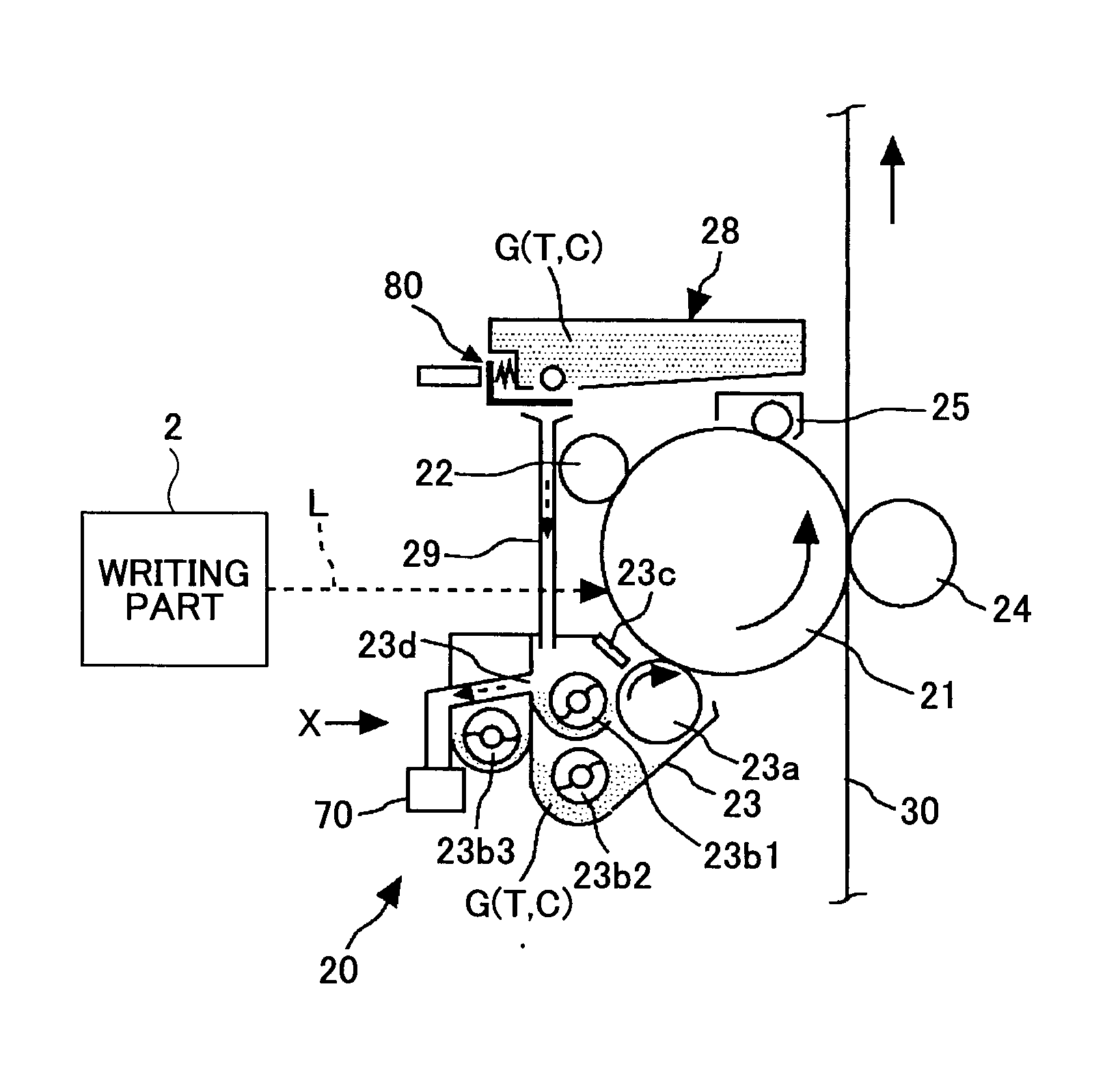
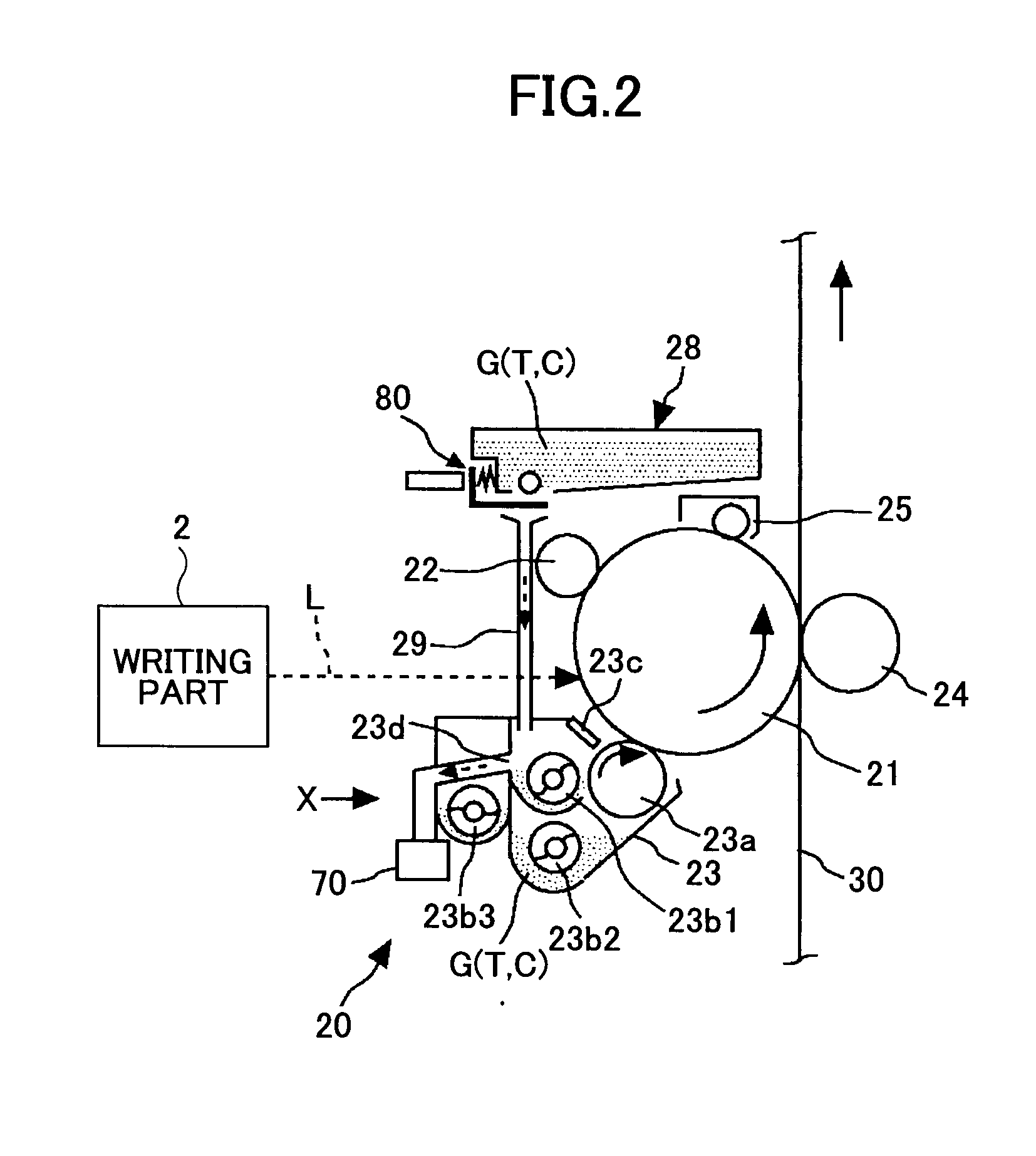
[0014]According to one or more embodiments of the present invention, there are provided a developing unit of the trickle development system where even if developer in the developing unit is inclined in an undulatory manner, no variation is caused in the amount of the developer discharged outside and the quality of an output image is stabilized, and a process cartridge and an image forming apparatus including the same.
[0019]According to one or more embodiments of the present invention, since there is provided a bypass channel for causing part of the developer to return to the upstream side of a circulation channel without passing a position where a discharge part is provided, it is possible to provide a developing unit of the trickle development system according to which no variation is caused in the amount of the developer discharged outside so that the quality of an output image is stabilized even if there is an undulatory inclination in the developer in the developing unit 23; and a process cartridge and an image forming apparatus including the developing unit.

Problems solved by technology

According to the above-described developing unit of the trickle development system of Japanese Laid-Open Patent Application No. 2001-183893, when driving of the unit is started, the developer in the unit may be inclined to locally cause great undulations on its surface, so that there may be an unintended discharge of the developer.
Repeated occurrence of such a phenomenon at every start and stop of the driving of the unit may cause an excessive discharge of the developer in the developing unit, thus causing a shortage of the amount of the developer.
This shortage of the amount of the developer in the developing unit causes the degraded condition of the developer to be unstable or the amount of electrostatic charge of toner to be reduced, thus causing a problem on an output image, such as a decrease in image density.

Method used


Image

  • Developing unit, process cartridge, and image forming apparatus
  • Developing unit, process cartridge, and image forming apparatus
  • Developing unit, process cartridge, and image forming apparatus

Examples


first embodiment

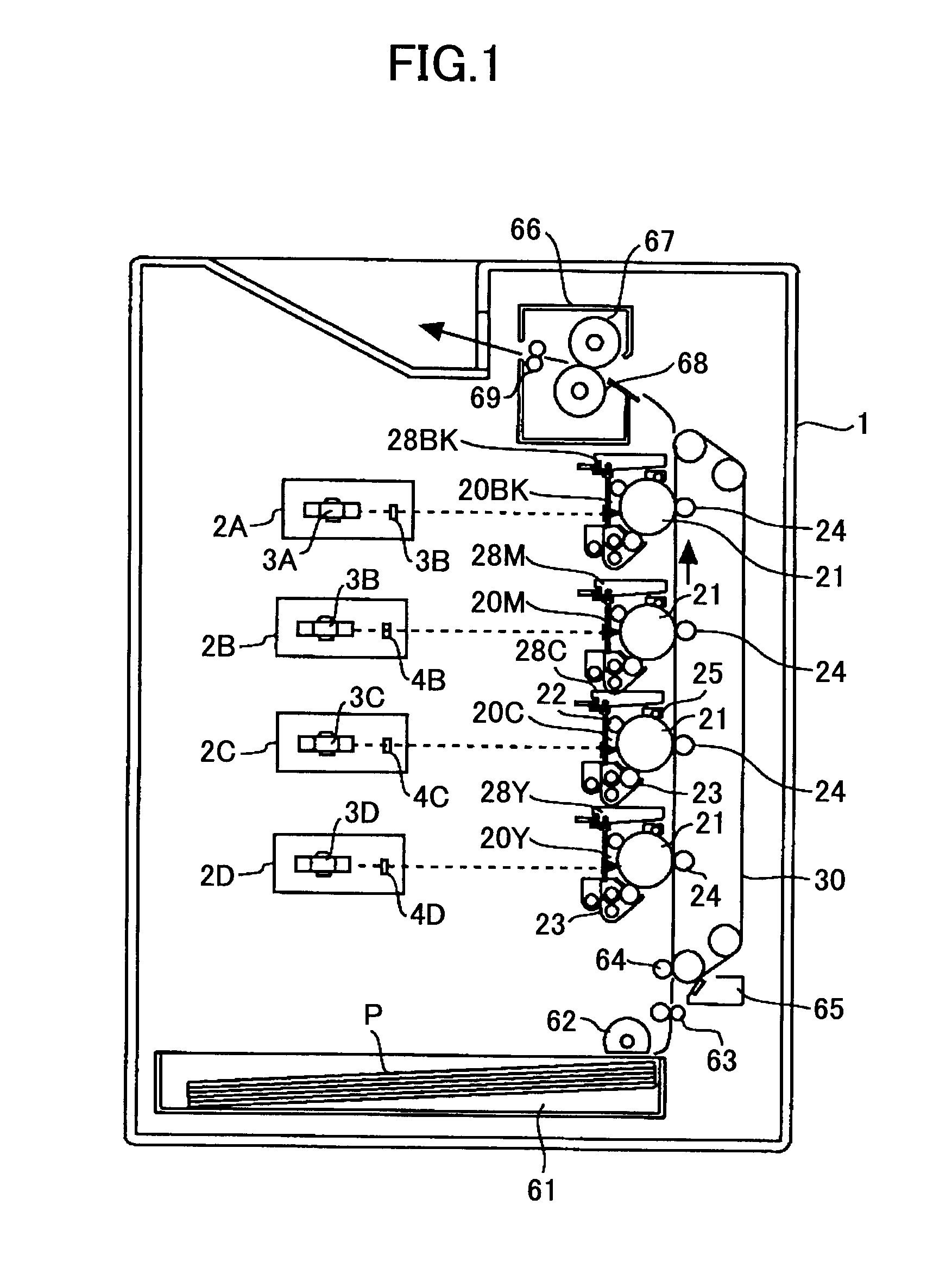
[0031]A description is given, with reference to FIG. 1 through FIG. 6, of a first embodiment of the present invention.

[0032]First, a description is given, with reference to FIG. 1, of an overall configuration and operation of an image forming apparatus according to the first embodiment of the present invention.

[0033]Writing parts 2A, 2B, 2C, and 2D are devices that write electrostatic latent images onto corresponding photosensitive body drums 21 (image carriers) after a charging process based on image information. The writing parts 2A through 2D are optical scanners using polygon mirrors 3A, 3B, 3C, and 3D and optical elements 4A, 4B, 4C, and 4D, respectively. Alternatively, the writing parts 2A through 2D may be LED arrays instead of optical scanners.

[0034]A paper feed part 61 contains transfer materials P such as OHP sheets and feeds the transfer materials P one by one to a transfer belt 30 at the time of forming an image.

[0035]The transfer belt 30, which is an endless belt for co...

second embodiment

[0093]A description is given, with reference to FIG. 7 through FIG. 9, of a second embodiment of the present invention.

[0094]FIG. 7 is a cross-sectional view of a developing unit 23A according to the second embodiment. FIG. 7 corresponds to FIG. 4 in the above-described first embodiment. One of the differences between the developing unit 23 of the first embodiment and the developing unit 23A of the second embodiment lies in that a projection part 23k is provided at the upper end of the discharge opening 23d in the developing unit 23A.

[0095]Like the developing unit 23 of the first embodiment, the developing unit 23A of this second embodiment also includes the discharge opening 23d as a discharge part and the opening 23e for returning part of the developer G to the conveyance channel by the third conveyor screw 23b3.

[0096]Here, according to the second embodiment, referring to FIG. 7, the projection part 23k (eaves) is provided at the upper end of the discharge opening 23d. This projec...


PUM


Abstract

A developing unit containing developer including carrier and toner and developing a latent image formed on an image carrier is disclosed. The developing unit includes multiple conveyor members configured to convey the contained developer in respective longitudinal directions so as to form a circulation channel; a supply part configured to supplement the carrier in the developing unit; a discharge part configured to discharge a first part of the contained developer outside the developing unit; and a bypass channel configured to cause a second part of the developer to return to the upstream side of the circulation channel without passing a position where the discharge part is provided.

Description

BACKGROUND OF THE INVENTION[0001]1. Field of the Invention[0002]The present invention relates generally to image forming apparatuses using electrophotography, such as copiers, printers, facsimile machines, and multifunction machines having two or more of their functions, and developing units and process cartridges provided therein, and more particularly to a developing unit of the trickle development system, which suitably supplies new carrier into the developing unit, and a process cartridge and image forming apparatus including the same.[0003]2. Description of the Related Art[0004]There is a conventionally known technique that suitably supplies new carrier to a developing unit containing two-component developer formed of toner and carrier (in some cases, with an additive added thereto) in image forming apparatuses such as copiers and printers, which technique is referred to as the trickle development system. (See, for example, Japanese Laid-Open Patent Application No. 2001-183893....

Claims


Application Information

Patent Timeline
Patent Type & Authority Applications(United States)
IPC IPC(8): G03G15/08
CPCG03G15/0822G03G2215/0838G03G2215/0819
Inventor TATEYAMA, SUSUMUFUJINUMA, YOSHITAKANAKAYAMA, MASAYOSHIKUBO, TATSUYA
Owner RICOH KK
Learn More