Wind Turbine, a Hub for a Wind Turbine and Use Hereof

a technology for wind turbines and hubs, which is applied in the direction of propellers, propulsive elements, water-acting propulsive elements, etc., can solve the problems of increasing the cost and overall weight of the wind turbine blade, and the weight of the arrangement has increased significantly

Active Publication Date: 2008-08-21
VESTAS WIND SYST AS
View PDF2 Cites 29 Cited by
  • Summary
  • Abstract
  • Description
  • Claims
  • Application Information

AI Technical Summary

Benefits of technology

[0061]The joint between the blades and the hub are usually under more strain on a variable speed pitch wind turbine, than on a fixed speed wind turbine, due to the

Problems solved by technology

Furthermore the use of material in the pitching arrangement and thus the weight of the arrangement has increased significantly with the increasing size of the modern wind turbine.
The blade design b

Method used


Image

  • Wind Turbine, a Hub for a Wind Turbine and Use Hereof
  • Wind Turbine, a Hub for a Wind Turbine and Use Hereof
  • Wind Turbine, a Hub for a Wind Turbine and Use Hereof

Examples


Embodiment Construction

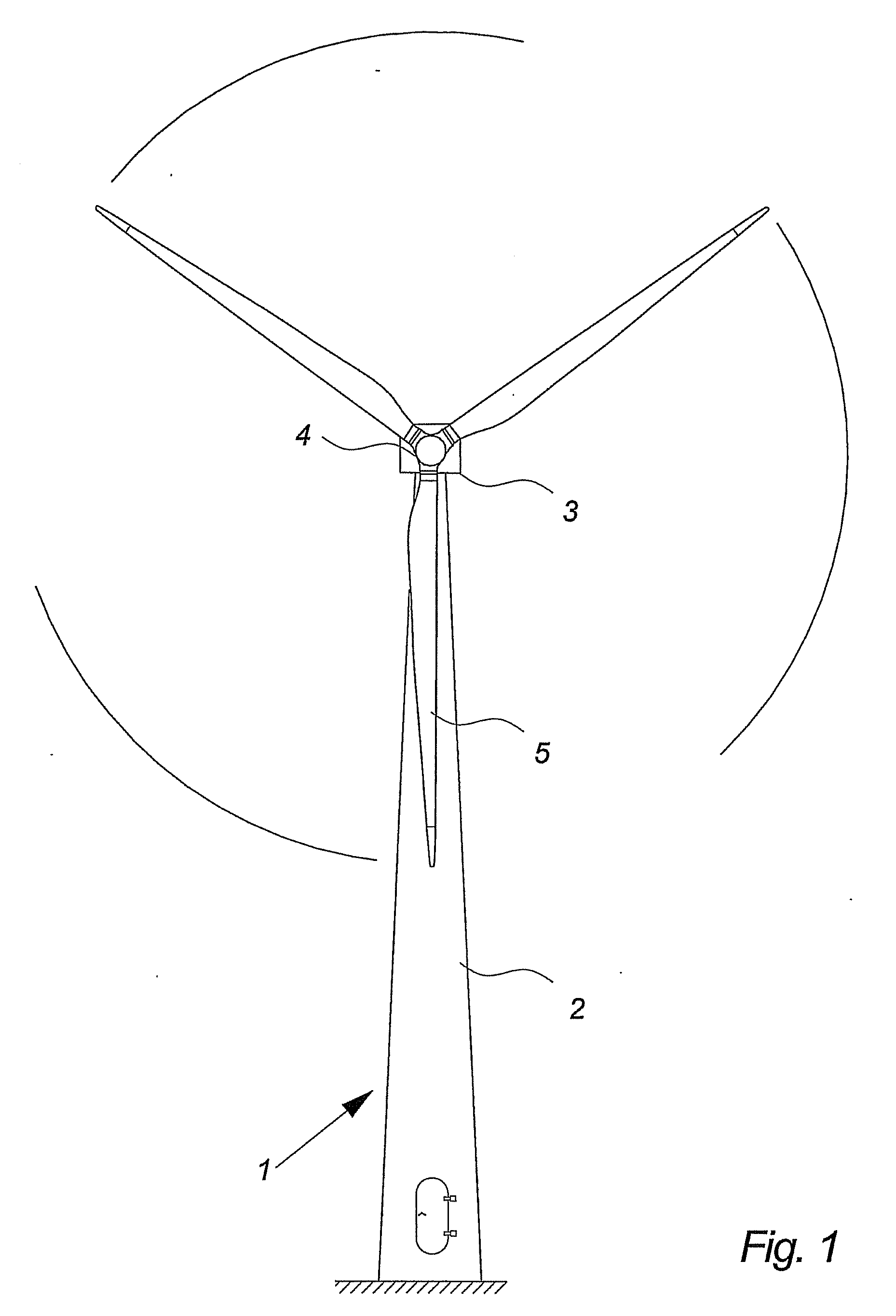
[0073]FIG. 1 illustrates a wind turbine 1, comprising a tower 2 and a wind turbine nacelle 3 positioned on top of the tower 2. The wind turbine rotor 4, comprising two wind turbine blades 5, is connected to the nacelle 3 through the low speed shaft which extends out of the nacelle 3 front.

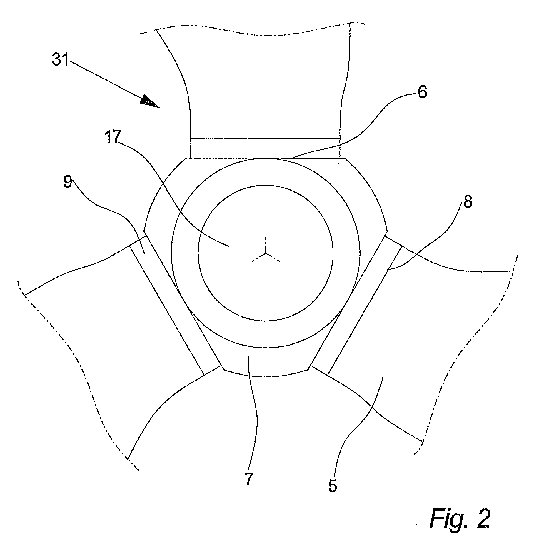
[0074]FIG. 2 illustrates a wind turbine hub 7 comprising three blades 5 as seen from the front. In this embodiment of the invention the hub 7 comprises three mount areas 6 for attachment of the blade units 31. Each blade unit 31 comprises a wind turbine blade 5 and a pitch bearing 9. The pitch bearing 9 is attached to the blade 5 and to the mount area of the hub 7 enabling the blade 5 to turn around its longitudinal axis.

[0075]In this embodiment of the invention the hub 7 further comprise an aperture 17 in the front part of the hub 7.

[0076]The pitch bearing 9 has to transfer forces mainly from three different sources. The blade 5 (and the bearings 9 themselves off cause) is under constant influence...


PUM


Abstract

The invention relates to a wind turbine including at least two blade units. Each blade unit has a pitch controlled wind turbine blade and at least one pitch bearing including at least one outer ring, at least one centre ring and at least one inner ring. The wind turbine further includes a hub comprising a mount area for each of the blade units (31). The mount area comprises at least two concentric load transferring surfaces for attaching the blade unit, via the at least one pitch bearing.
The invention further relates a hub and a use hereof.

Description

TECHNICAL FIELD OF THE INVENTION [0001]The invention relates to a wind turbine, a hub for a wind turbine and use hereof.DESCRIPTION OF THE RELATED ART [0002]A wind turbine known in the art comprises a wind turbine tower and a wind turbine nacelle positioned on top of the tower. A wind turbine rotor with three wind turbine blades is connected to the nacelle through a low speed shaft, as illustrated on FIG. 1.[0003]Modern wind turbines control the load on the rotor by pitching the blades in and out of the incoming wind. The blades are pitched to optimize the output or to protect the wind turbine from damaging overloads.[0004]To perform the pitch each blade is provided with a pitching arrangement comprising a pitch bearing between the hub and the blade, and some sort of mechanism, most often a hydraulic cylinder, to provide the force for pitching the blade and maintaining it in a given position. This pitching arrangement enables each blade to be turned approximately 90° around their lo...

Claims


Application Information

Patent Timeline
IPC IPC(8): F03D1/06F03D11/00
CPCF03D1/0658F03D7/0224F03D11/0008F05B2260/79F16C19/10Y02E10/723F16C19/381F16C19/50F16C2300/14Y02E10/721Y02E10/722F16C19/18F03D80/70F16C2360/31Y02E10/72F16C19/505
Inventor BECH, ANTON
Owner VESTAS WIND SYST AS
Why Eureka
Try Eureka