

Article for Stamping
- Summary
- Abstract
- Description
- Claims
- Application Information
AI Technical Summary
Benefits of technology
Problems solved by technology
Method used
Image

Examples
Embodiment Construction
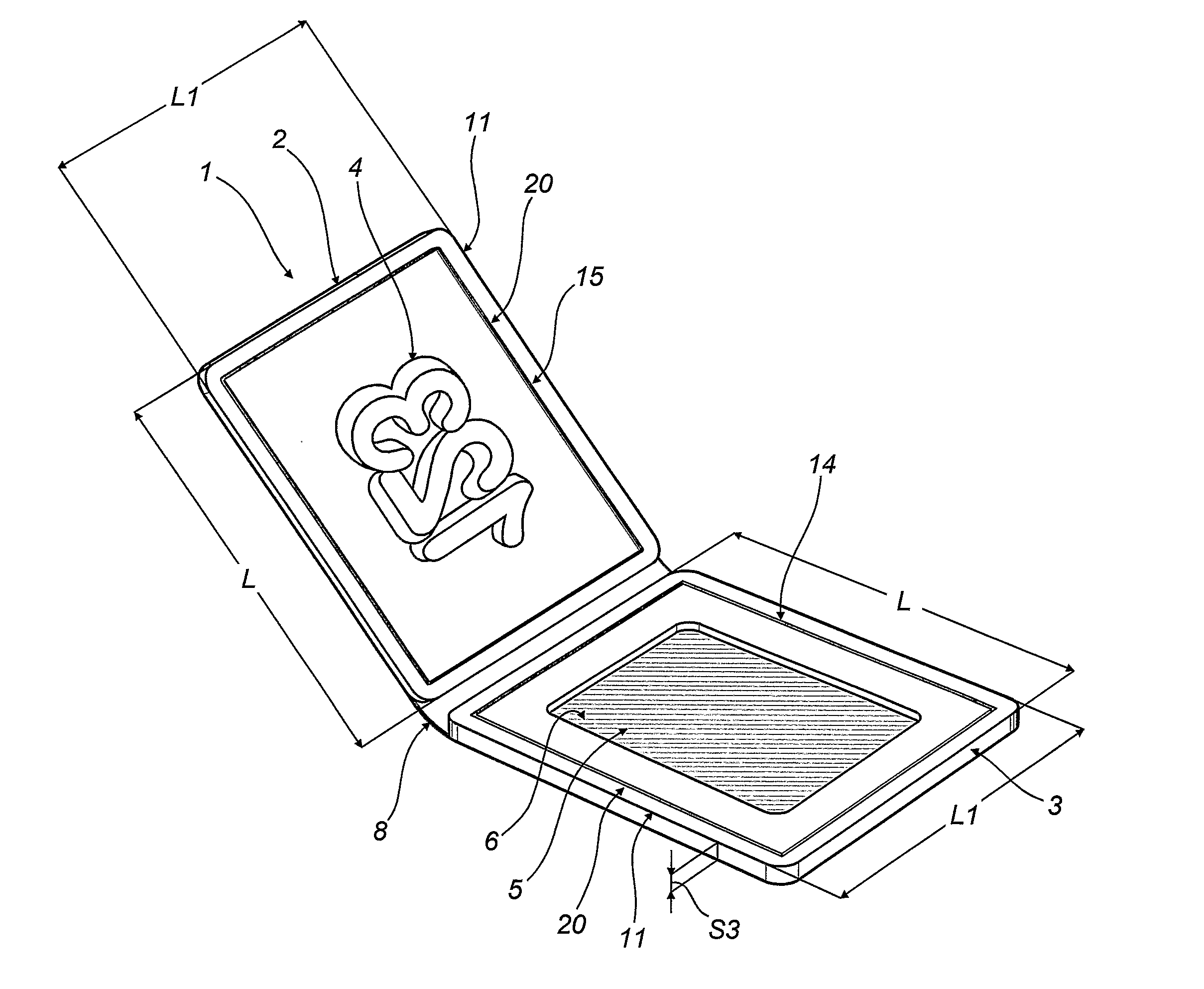
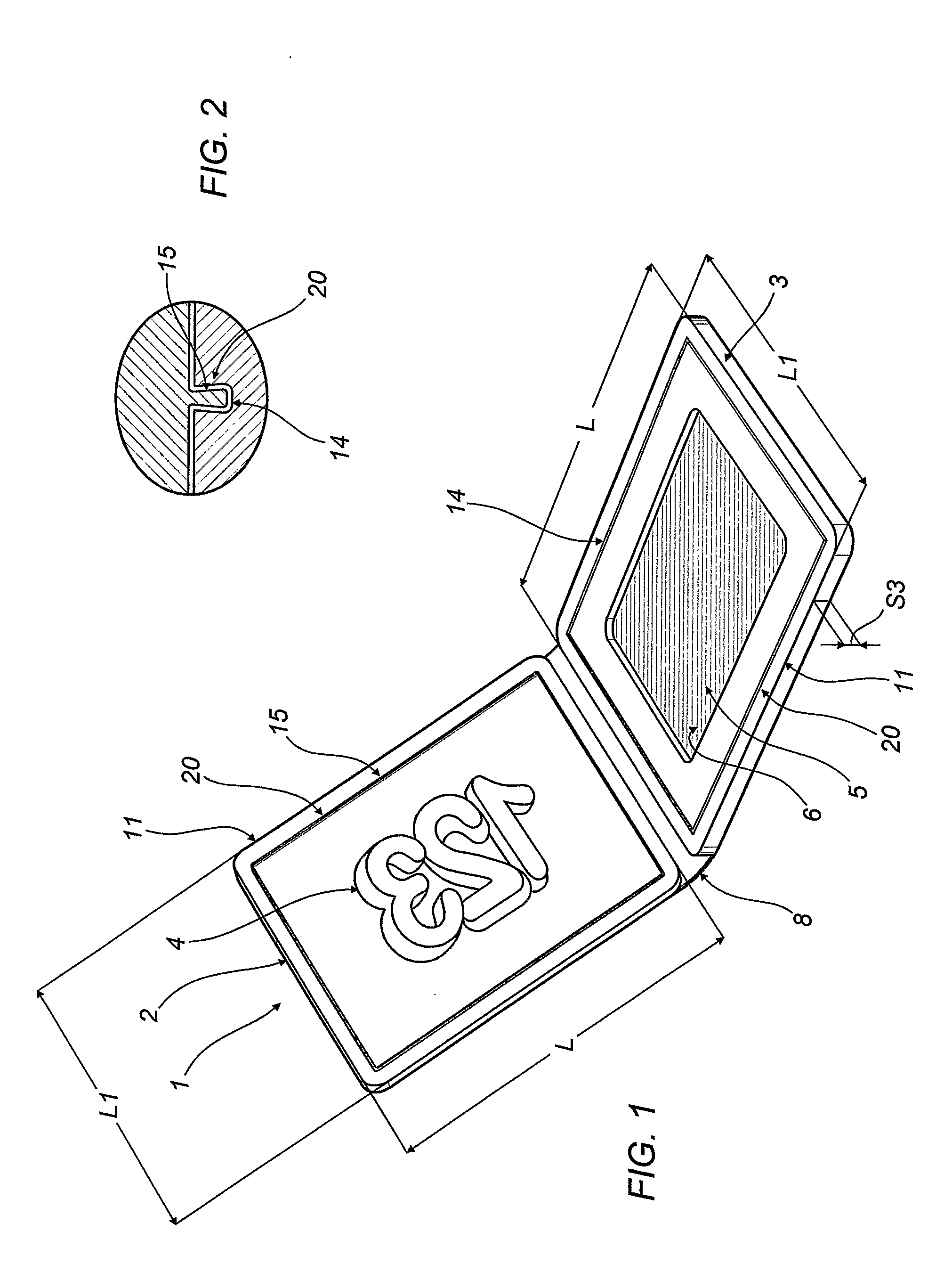
[0034]With reference to the accompanying drawings, the numeral 1 denotes an article for stamping in accordance with the present invention, in a partly open configuration.
[0035]The article 1 comprises a first and a second laminar element 2, 3 hinged together.
[0036]The elements 2 and 3 can move relative to one another between a closed configuration in which they are positioned on top of one another, illustrated in FIG. 5, relative to the solution from FIG. 3, and an open configuration, illustrated in FIGS. 4, 6, 7 and 9.
[0037]As illustrated in particular in FIG. 1, the elements 2 and 3 are made in a single body, for example by moulding, and are separated by a portion of material 8 with reduced thickness forming a hinge for rotation of the elements 2 and 3 relative to one another.
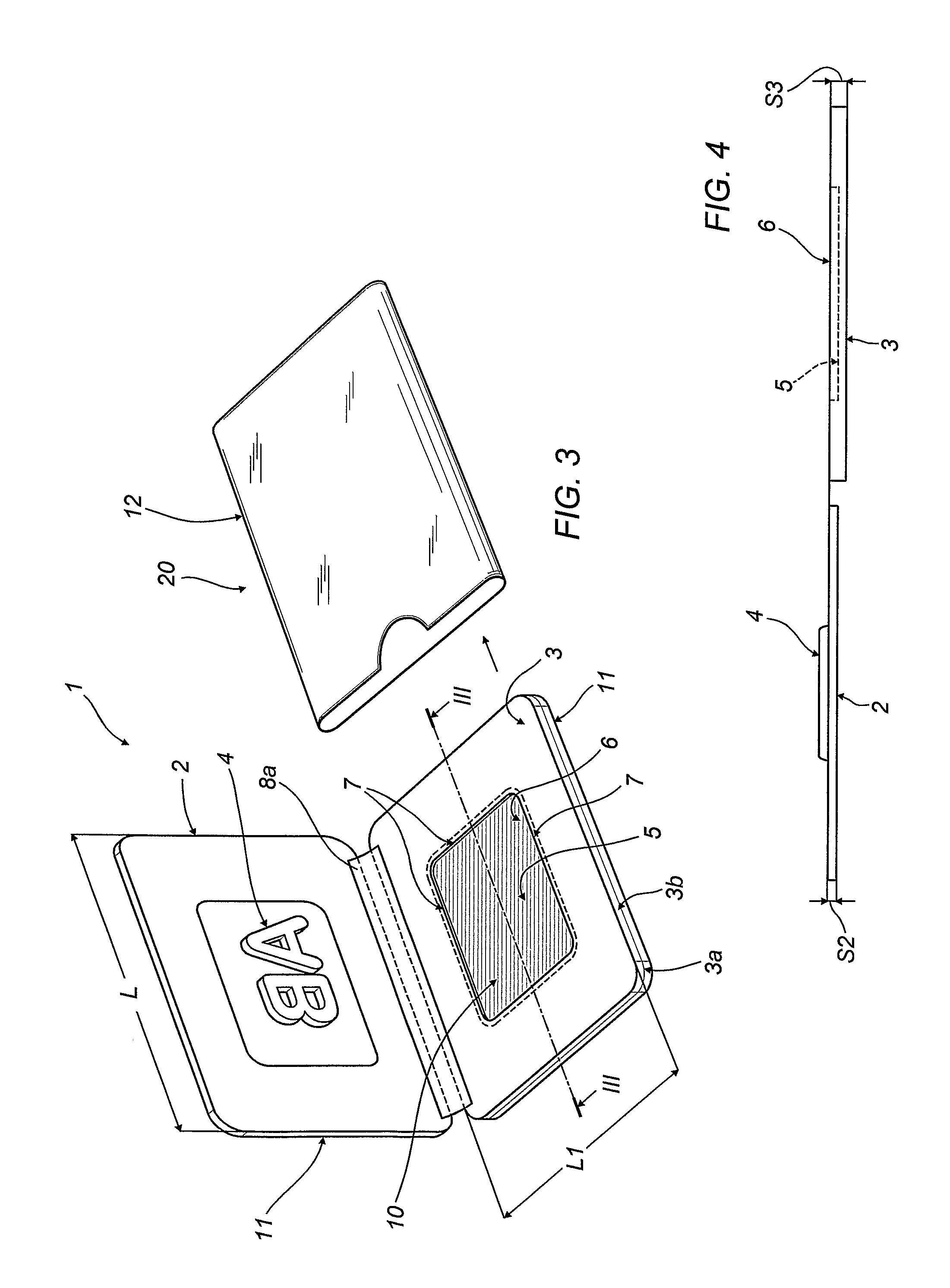
[0038]As illustrated in FIG. 3, the elements 2 and 3 are hinged together by an adhesive strip 8a, which may be doubled on the other side of the elements 2 and 3 by a similar strip, not illustrated.
[0039]A rais...
PUM
 Abstract
Description
Claims
Application Information