Electromagnetic Compliance Spring of Drive Carrier

a technology of electromagnetic emission and compliance spring, which is applied in the direction of electrical equipment, screening gaskets/seals, and screening casings, etc., can solve the problems of carrier electromagnetic emission, increased difficulty in shielding drives such as disk drives, and interference with the frequency used by telecommunications, so as to block electromagnetic emission of computing devices

Inactive Publication Date: 2008-08-28
IBM CORP
View PDF14 Cites 20 Cited by
  • Summary
  • Abstract
  • Description
  • Claims
  • Application Information

AI Technical Summary

Benefits of technology

[0007]Embodiments may include a method to block electromagnetic emissions of a computing device. The method may include fastening a spring finger to a drive carrier, inserting the drive carrier into a drive bay of the computing device, contacting a drive adjoining ...

Problems solved by technology

If not prevented from escaping, this radiation may interfere with standard frequencies used for telecommunications such as the frequencies used for television and cell phones.
Advancing technology makes the shielding of drives, such as disk drives, increasingly difficult.
The stiffness of many current EMC spring finger designs may cause problems.
With some spring systems, the carriers may require significant insertion forces.
When these carriers are installed into systems, their stiff springs may scrape forcefully along the bottom of the disk drives above them, stripping off components or damaging the springs themselves.
These metal covers, even though perforated, may s...

Method used


Image

  • Electromagnetic Compliance Spring of Drive Carrier
  • Electromagnetic Compliance Spring of Drive Carrier
  • Electromagnetic Compliance Spring of Drive Carrier

Examples


Embodiment Construction

[0020]The following is a detailed description of embodiments of the invention depicted in the accompanying drawings. The embodiments are in such detail as to clearly communicate the invention. However, the amount of detail offered is not intended to limit the anticipated variations of embodiments; but on the contrary, the intention is to cover all modifications, equivalents, and alternatives falling within the spirit and scope of the present invention as defined by the appended claims. The detailed descriptions below are designed to make such embodiments obvious to a person of ordinary skill in the art.

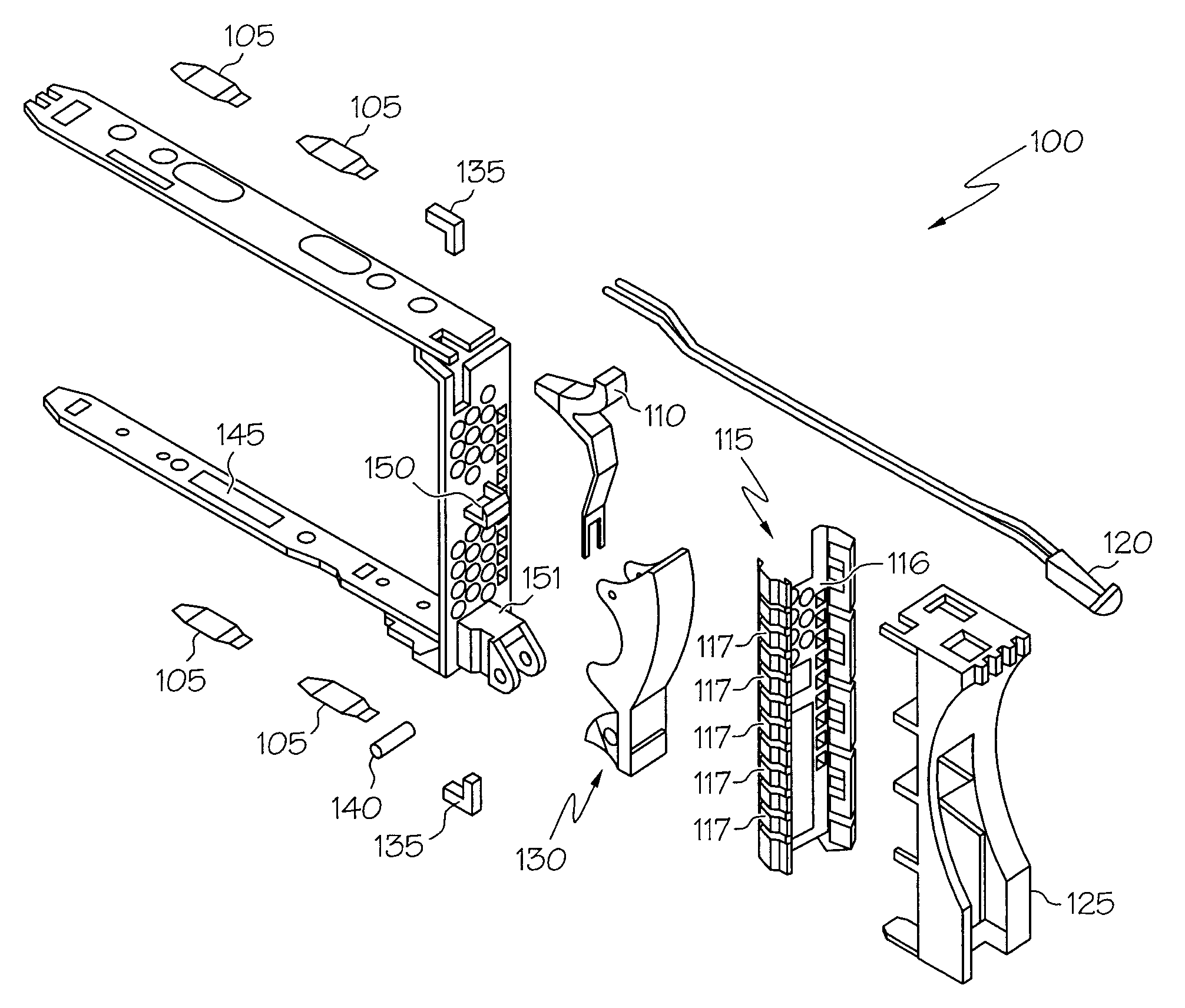
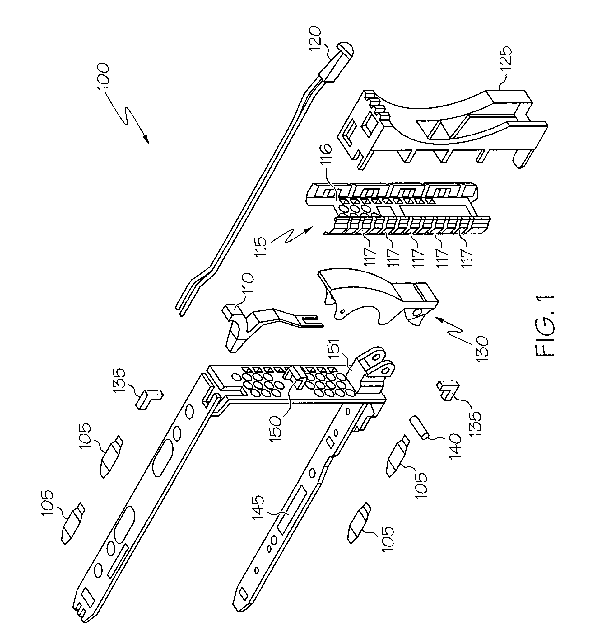
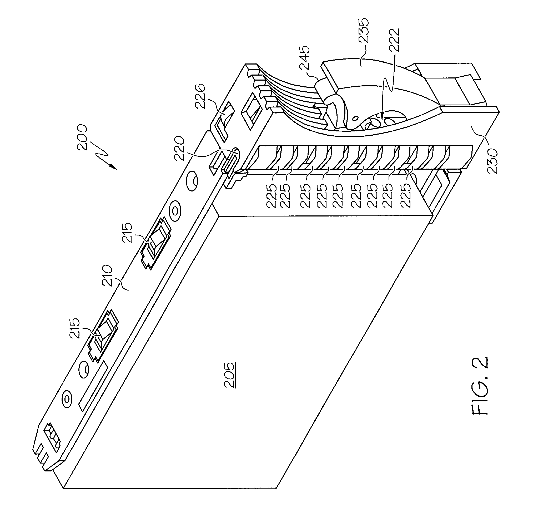
[0021]Generally speaking, systems, methods, and apparatus to provide electromagnetic compliance (EMC) for a drive carrier are disclosed. Embodiments may include an EMC spring. The EMC spring may include a shield portion to fasten to one side of a frame of the drive carrier and multiple fingers attached to the shield portion. At least one of the fingers may include an upper spring sect...


PUM


Abstract

Systems and arrangements to provide electromagnetic compliance (EMC) for a drive carrier are disclosed. Embodiments may include an EMC spring. The EMC spring may include a shield portion to fasten to one side of a frame of the drive carrier and multiple fingers attached to the shield portion. At least one of the fingers may include an upper spring section to contact an adjoining drive carrier as the drive carrier is inserted into a computing device and a lower spring section. The lower spring section may be folded over against the upper spring section and attached to the shield portion of the spring. The lower spring section may deflect in response to the upper spring section contacting the adjoining drive carrier. In some embodiments, a lead in portion of the upper spring section may deflect to a position nearly parallel to the adjoining drive carrier.

Description

FIELD[0001]The present invention generally relates to the field of reducing electromagnetic emissions from computing devices. More particularly, the present invention relates to an electromagnetic compliance spring for a drive carrier.BACKGROUND[0002]The passage of electrical currents through computing equipment may produce electromagnetic radiation. If not prevented from escaping, this radiation may interfere with standard frequencies used for telecommunications such as the frequencies used for television and cell phones. Accordingly, regulatory agencies, such as the Federal Communications Commission and the International Special Committee on Radio Interference (Comite Internationale Special Preturbation Radioelectrique), require the makers of computing equipment to provide shielding for the electromagnetic radiation. The shielding may reflect or absorb the radiation. Electromagnetic compatibility (EMC) techniques attempt to comply with the regulations.[0003]One type of electromagn...

Claims


Application Information

Patent Timeline
IPC IPC(8): H05K9/00
CPCH05K9/0016G11B33/12
Inventor GALLARELLI, PATLUND, DAVID G.MILLER, MICHAEL S.TUMA, CHRISTOPHER L.
Owner IBM CORP
Why Eureka
Try Eureka