Visual preview for laser fabrication

a laser fabrication and laser technology, applied in auxillary welding devices, program control, instruments, etc., can solve the problems of difficult light entering or escaping the unit safely, particularly challenging design constraints, and easy misdirection of laser cutter/engraver beams, so as to prevent the emission of electromagnetic energy

Active Publication Date: 2017-02-16
GLOWFORGE
View PDF6 Cites 69 Cited by
  • Summary
  • Abstract
  • Description
  • Claims
  • Application Information

AI Technical Summary

Benefits of technology

[0006]In another aspect, a computer numerically controlled machine includes a movable head configured to deliver electromagnetic energy to a part of a working area defined by limits within which the movable head is commanded to cause delivery of the electromagnetic energy. The working area is inside an interior space of the laser computer numerically controlled machine. The interior space is defined by a housing includes an openable barrier that attenuates transmission of light between the interior space and an exterior of the computer numerically controlled machine when the openable barrier is in a closed position. The commanding results in the computer numerically controlled machine executing operations of a motion plan for causing movement of the movable head to deliver the electromagnetic energy to effect a change in a material at least partially contained within the interior space.
[0007]Emission of the electromagnetic energy is temporarily prevented. Also, an image including at least half of the working area with at least one camera is be generated. The generating occurs when the openable barrier is in the closed position and during the temporality preventing of the emission of the electromagnetic energy.

Problems solved by technology

While laser cutter / engravers share some common features with CNC machines, they have many differences and present particularly challenging design constraints.
A laser cutter / engraver is subject to regulatory guidelines that restrict the egress of electromagnetic radiation from the unit when operating, making it challenging for light to enter or escape the unit safely, for example to view or record an image of the contents.
The beam of a laser cutter / engraver is easily misdirected, with a small angular deflection of any component relating to the beam path potentially resulting in the beam escaping the intended path, potentially with undesirable consequences.
Airflow is important in laser cutter / engraver designs, as air may become contaminated with byproducts of the laser's interaction with the material such as smoke, which may in turn damage portions of the machine for example fouling optical systems.
Unlike most machining tools, the kerf the amount of material removed during the operation—is both small and variable depending on the material being processed, the power of the laser, the speed of the laser, and other factors, making it difficult to predict the final size of the object.
Also unlike most machining tools, the output of the laser cutter / engraver is very highly dependent on the speed of operation; a momentary slowing can destroy the workpiece by depositing too much laser energy.
This limitation is modeled in the motion planner and affects the motion plan.
Error conditions can be identified, such as if a foreign body has been inadvertently left in the CNC machine 100, the material has been inadequately secured, or the material is reacting in an unexpected way during machining.
In some implementations, image processing capability can be performed by the CNC machine 100, but with limited speed.
One example of this can be where the onboard processor is slow and can run only simple algorithms in real-time, but which can run more complex analysis given more time.
In these cases, limited image processing can be done locally, with more detailed image processing and analysis being done remotely.
In another example, if the machine is a laser cutter / engraver and activating the laser causes a camera located in the head to become overloaded and useless, footage from that camera may be discarded when it is unavailable.
In another example, recording of video might cease if an error condition is detected, such as the lid being opened unexpectedly during a machining operation.
Particularly in the case of cameras with a wide-field of view, there can be obstructions in the images acquired with these cameras.
If the wrong size of raw material is inserted, for example if the material is too tall, the head may collide with it.
In another example, there may be unaccounted-for material such as clamps in the workspace.
It is common for there to be collisions between the head and such items, resulting in damage.
If the machine will intersect the material at a speed that is unsafe, or move the spinning bit through too much material, it is also an error state.
Normally this is difficult because any disturbance of the material 140 means that subsequent processing operations are not aligned with the operations performed so far.
The cameras can also detect a buildup of smoke, indicating a failure of the exhaust system.
A principal challenge of wide-angle imaging inside a small working space with the unit closed is the distortion introduced by the wide-angle lens required.
Images from cameras, particularly those with a wide field of view, can suffer from multiple types of distortions.
The distortions can be due to optical components in a camera, such as a wide angle lens, the de-centration of an imaging sensor within said lens, chromatic aberrations, reflections or reflectivity, damage or undesirable coatings on the lens, etc.

Method used


Image

  • Visual preview for laser fabrication
  • Visual preview for laser fabrication
  • Visual preview for laser fabrication

Examples


Embodiment Construction

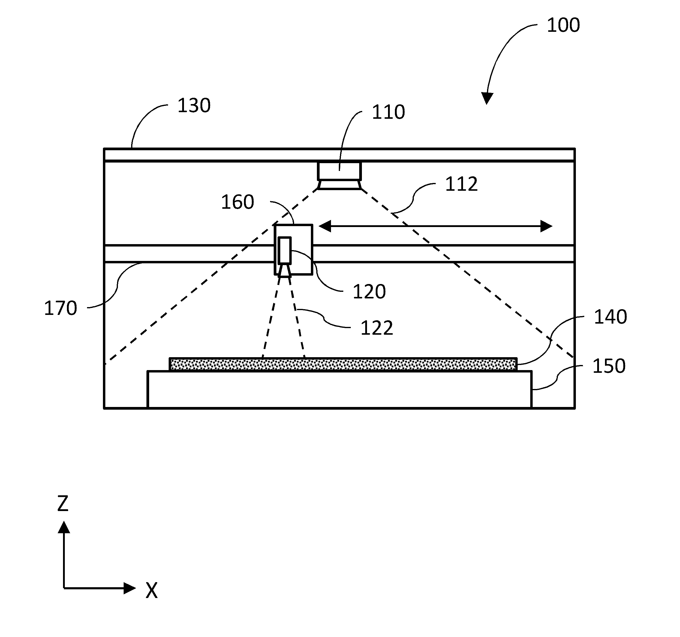
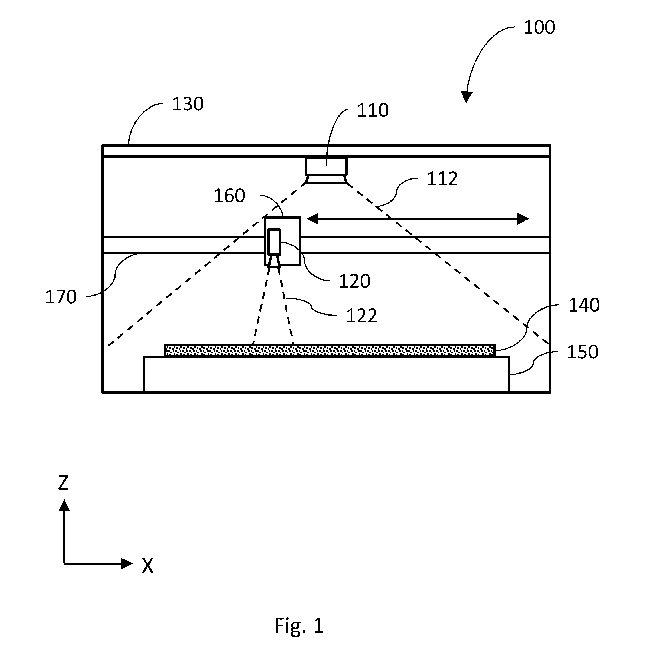
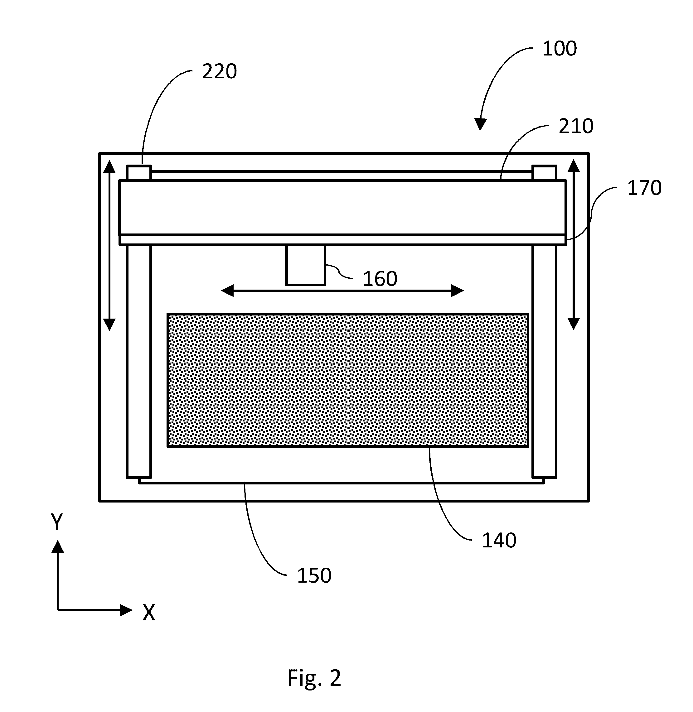
[0040]The details of one or more variations of the subject matter described herein are set forth in the accompanying drawings and the description below. Other features and advantages of the subject matter described herein will be apparent from the description and drawings, and from the claims. While certain features of the currently disclosed subject matter may be described for illustrative purposes in relation to using machine-vision for aiding automated manufacturing processes (e.g. a CNC process), it should be readily understood that such features are not intended to be limiting.

[0041]As used herein, the term “cutting” can generally refer to altering the appearance, properties, and / or state of a material. Cutting can include, for example, making a through-cut, engraving, bleaching, curing, burning, etc. Engraving, when specifically referred to herein, indicates a process by which a CNC machine modifies the appearance of the material without fully penetrating it. For example, in t...


PUM

PropertyMeasurementUnit
speedaaaaaaaaaa
speedaaaaaaaaaa
thicknessaaaaaaaaaa

Abstract

A computer numerically controlled machine may include a movable head configured to deliver electromagnetic energy to a part of a working area in which the movable head may be commanded to cause delivery of the electromagnetic energy. The interior space may be defined by a housing and may include an openable barrier that attenuates transmission of light between the interior space and an exterior of the computer numerically controlled machine when the openable barrier is in a closed position. The computer numerically controlled machine may include an interlock that prevents emission of the electromagnetic energy when detecting that the openable barrier is not in the closed position. The commanding may result in the computer numerically controlled machine executing operations of a motion plan for causing movement of the movable head to deliver the electromagnetic energy to effect a change in a material at least partially contained within the interior space.

Description

CROSS-REFERENCE TO RELATED APPLICATIONS[0001]The current application claims priority to U.S. Provisional Patent Application No. 62 / 115,562 filed Feb. 12, 2015; U.S. Provisional Patent Application No. 62 / 115,571 filed Feb. 12, 2015; U.S. Provisional Patent Application No. 62 / 222,756 filed Sep. 23, 2015; U.S. Provisional Patent Application No. 62 / 222,757 filed Sep. 23, 2015; and U.S. Provisional Patent Application No. 62 / 222,758 filed Sep. 23, 2015. The written description, claims, and drawings of all of the aforementioned applications are incorporated herein by reference.TECHNICAL FIELD[0002]The subject matter described herein relates to manufacturing processes implementing, or aided by, machine vision incorporating a wide-angle viewing system inside the manufacturing machine.BACKGROUND[0003]Computer controlled manufacturing systems, such as “3-D printers,” laser cutter / engravers, CNC milling machines, and the like, can be used to create complicated items where traditional manufactur...

Claims


Application Information

Patent Timeline
Patent Type & Authority Applications(United States)
IPC IPC(8): G05B19/402
CPCG05B19/402G05B2219/36199G05B2219/45212G05B2219/32001B23K26/032B23K26/08B23K26/0853B23K26/38B23K37/0235G05B19/406B23K26/00B23K26/702G05B2219/31186G05B2219/36053G05B2219/37359G05B2219/37555G05B2219/45041G05B2219/42307B33Y50/00Y02P80/40B23K37/0211B23K37/0408B23K26/082B29C64/393Y02P90/80B27M1/08G05B19/18B23K10/006B23Q17/22G06F21/121B23K26/0876
Inventor SHAPIRO, DANIELGOSSELIN, MARKWRIGHT, ANTHONYPUTNEY, DEANELLIS, TIMOTHYBANKA, LAUREN
Owner GLOWFORGE
Why Eureka
Try Eureka