Automatic parking system based on mobile robot trolley

A mobile robot and automatic parking technology, applied in the field of parking systems, can solve the problems of high maintenance cost, large maintenance volume, waiting in line, etc., and achieve the effect of increasing the overall space area, saving emission fees, and narrowing the emission distance.

Active Publication Date: 2012-07-04
SHENZHEN PUZHILIANKE ROBOT TECH CO LTD
View PDF9 Cites 78 Cited by
  • Summary
  • Abstract
  • Description
  • Claims
  • Application Information

AI Technical Summary

Problems solved by technology

The existing problems are: (1) This kind of robot is a kind of robot in a broad sense and cannot be separated independently. The walking of the robot must rely on the guide rail of the crane and along the elevator and related motors, gears, chain drives, sheave sets, and wire ropes. The transmission device has a complex structure; (2) Although the robot solves the problem of automatic storage and retrieval of vehicles, the implementation of the scheme requires a lot of construction: relevant crane guide rails, lifting devices and transmission devices must be erected; (3) the robot is affected by the sky. The limitation of the vehicle guide rail can only solve the access problem of the single-row vehicles on both sides of the guide rail nearby, but for the vehicles far away from the guide rail, such as the second or third row on both sides of the guide rail, there is nothing to do
The existing problem is: the parking lot is still inseparable from the mechanized transmission mode, not only the construction volume is large, such as the laying of tracks, elevators, transmission devices, etc. must be installed, but also the elevator and track walking mode lead to high cost, obvious power consumption, The amount of maintenance is large, and a failure of a certain link in the system will lead to the paralysis of the entire system; not only that, but the mechanized three-dimensional parking lot seen on the market is generally for the access of single-row vehicles on both sides of the track, rather than for multiple parking lots. row of vehicles, therefore, its auxiliary space area is reduced to 1 / 3 at most
[0005] To sum up, the above two methods illustrate the typical weaknesses of the mechanized three-dimensional parking lot: (1) The storage position of the vehicle is limited by the track, and must be close to the sides of the track and the place where the lift is easy to reach, which forms a three-dimensional parking garage. Increase the parking space, or develop upwards, or develop towards slenderness, and the ensuing problems are: the auxiliary space also increases synchronously, the amount of steel and civil engineering used to lay the track also increases synchronously, and the amount of mechanical wear, power consumption, and maintenance The volume also increases simultaneously
(2) The operating equipment of the existing three-dimensional mechanical parking lot is a serial working mode whether it is lifting displacement or horizontal displacement. The same equipment is working from the beginning to the end, and it cannot take advantage of the coordination of multiple equipment Advantage, when several car owners access the vehicle at the same time, there will be waiting in line
(3) The existing three-dimensional mechanical parking lot is limited by its design method. Its lifting mechanism is huge and heavy, and it is not easy to disassemble and replace at any time. Once a certain part is removed, the entire system will be paralyzed
(4) The construction and maintenance costs of the existing three-dimensional mechanical parking lot are relatively high, and it is difficult to meet the actual needs

Method used


Image

  • Automatic parking system based on mobile robot trolley
  • Automatic parking system based on mobile robot trolley
  • Automatic parking system based on mobile robot trolley

Examples


Embodiment Construction

[0038] Embodiments of the present invention are described in further detail below in conjunction with the accompanying drawings:

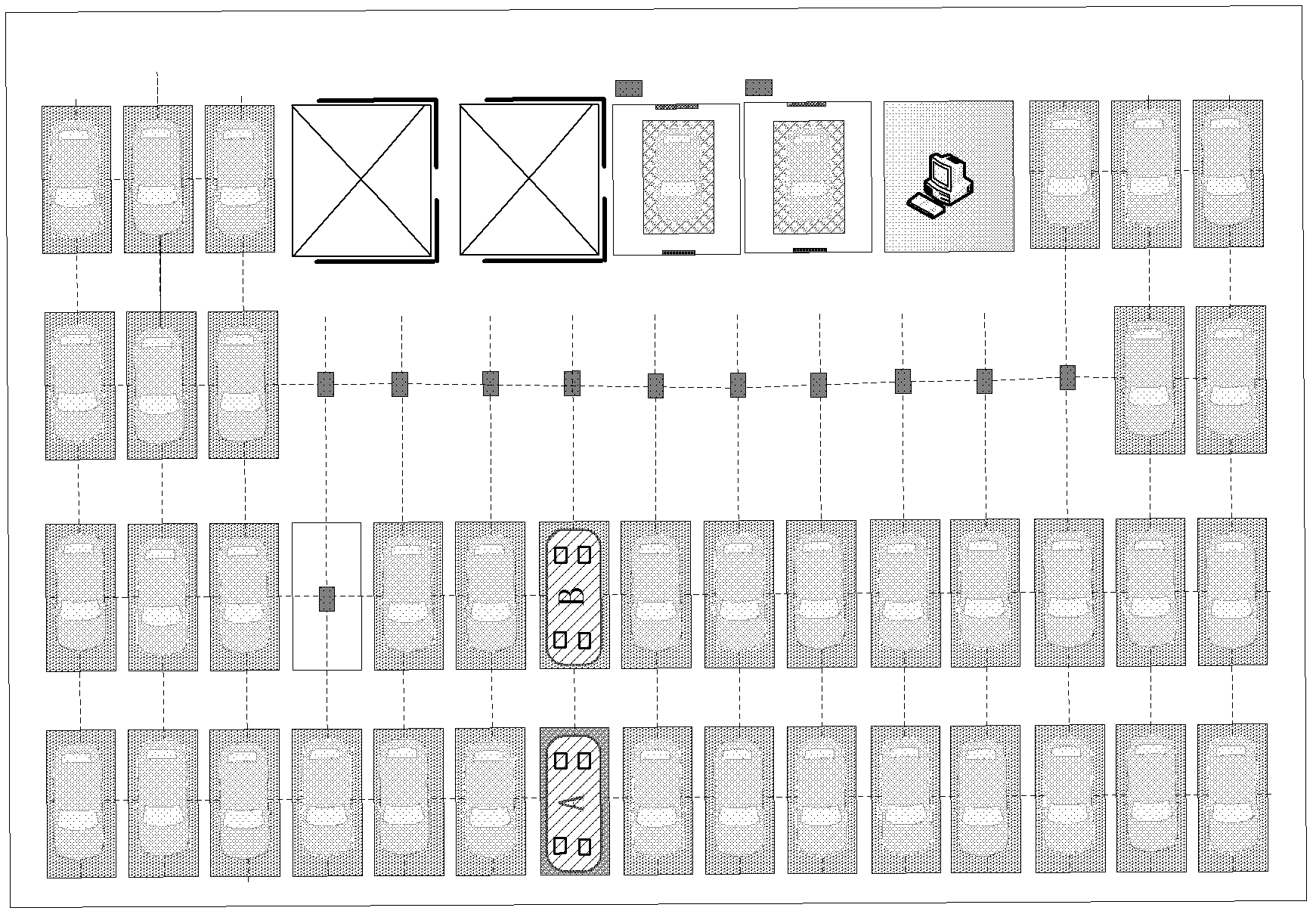
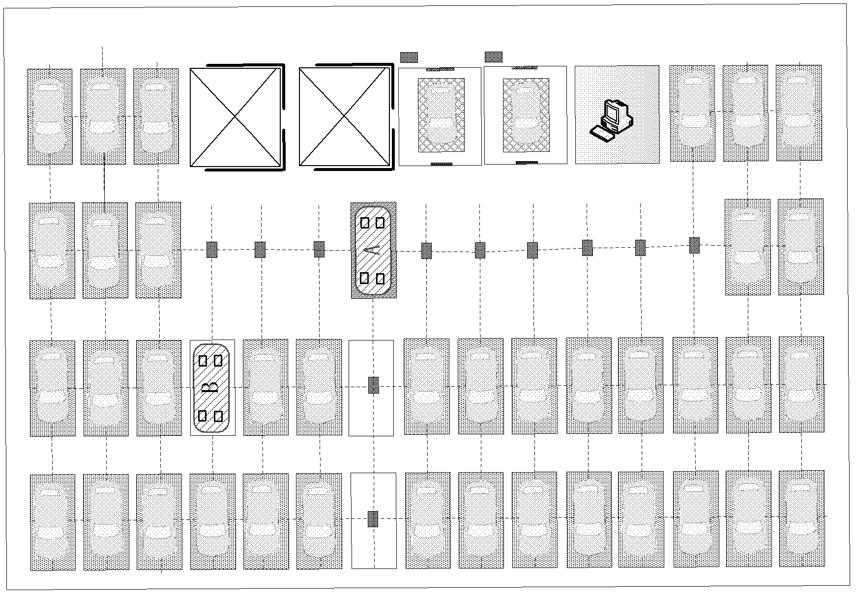
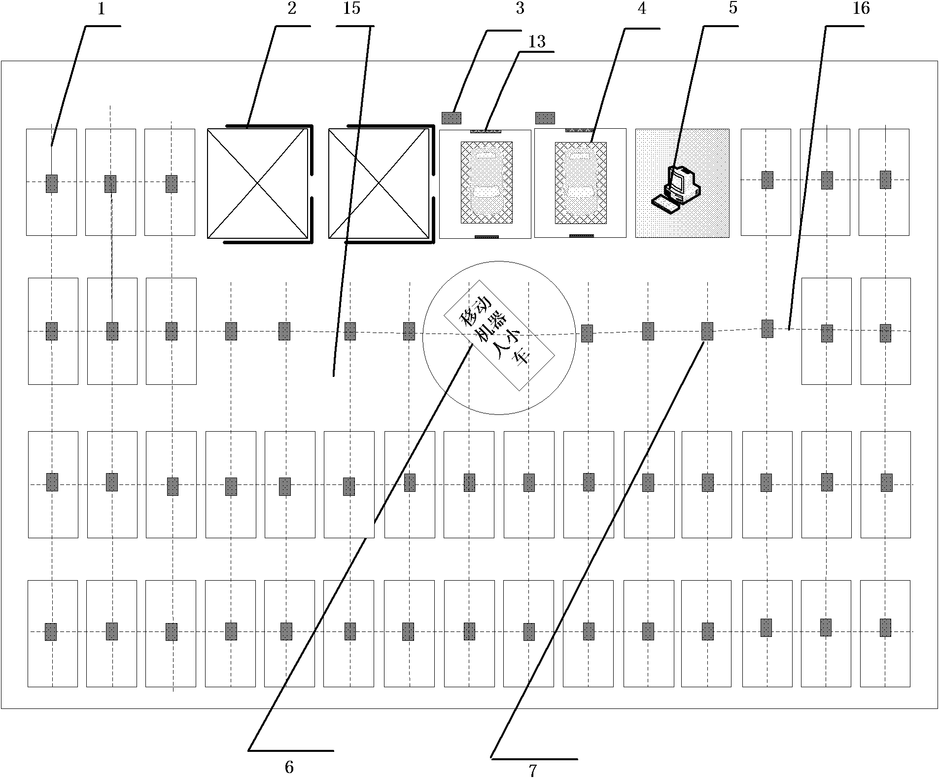
[0039] An automatic parking system based on a mobile robot car, such as figure 1 and figure 2 As shown, it consists of a three-story parking lot, a vehicle access room, an elevator, a central control room, several mobile robot cars and an intelligent control system for the parking lot. The N-story parking lot can be set at any position on the ground, underground or semi-ground. Two elevators are installed in the parking lot for the transportation of vehicles to be accessed between the parking lots on each floor; several mobile robot cars and corresponding car rotating spaces are arranged in each parking lot, There are two vehicle access rooms and a central control room in the parking lot, and the parking lot intelligent control system is installed in the central control room.

[0040] A non-track vehicle guiding device is laid on the ground of ...


PUM


Abstract

The invention relates to an automatic parking system based on a mobile robot trolley. The automatic parking system is mainly and technically characterized by comprising a parking lot, the mobile robot trolley and a parking lot intelligent control system, wherein a plurality of rows of parking spaces, a plurality of lines of parking spaces and mobile robot trolley rotating spaces are arranged on the ground of the parking lot, a non-rail type vehicle guide device is paved on the ground of the parking lot, a vehicle access chamber and a center control chamber are arranged in the parking lot, the parking lot intelligent control system is arranged in the center control chamber and is connected with the mobile robot trolley and the vehicle access chamber, and the mobile robot trolley supports vehicles to be accessed for realizing the vehicle access through being controlled by the parking lot intelligent control system. The automatic parking system has the advantages that the design is reasonable, and the flexible dispatching on the vehicles to be accessed and the flexible vehicle access can be carried out through the mobile robot trolley and the corresponding control system, so the functions of high-density storage, fast response and safe service are realized, and the automatic parking system has the characteristics that the building and maintenance cost is low, the access is convenient, the energy is saved, the environment is protected, and the like.

Description

technical field [0001] The invention belongs to the field of parking systems, in particular to an automatic parking system based on a mobile robot trolley. Background technique [0002] With the rapid popularization and development of automobiles, the supply of urban parking spaces is seriously insufficient, and car parking lots are gradually developing into mechanized three-dimensional parking lots. The existing parking lot mainly has the following structures: [0003] 1. The patent document "Intelligent Robot Stereoscopic Parking Lot" (application number 01138703.3) discloses a rectangular three-dimensional parking lot based on an intelligent robot. The parking lot uses robotic access vehicles instead of manual access vehicles, which solves the problem to a certain extent. The auxiliary area of ​​the traditional parking lot is larger than the parking area, and the auxiliary area is reduced from 2 / 3 to 1 / 3. The existing problems are: (1) This kind of robot is a kind of ro...

Claims


Application Information

Patent Timeline
Patent Type & Authority Applications(China)
IPC IPC(8): E04H6/18E04H6/22E04H6/28E04H6/42
Inventor 刘辉
Owner SHENZHEN PUZHILIANKE ROBOT TECH CO LTD
Why Eureka
Try Eureka